

|
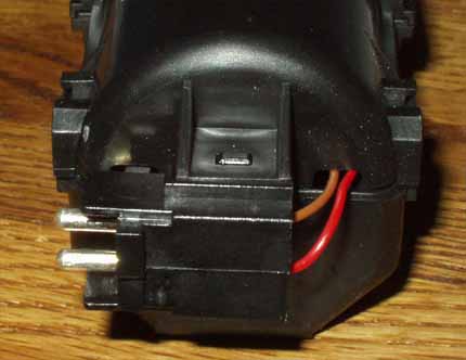
A/C Technical Tips, 1986-91 5000/200TQ Important Safety Information A/C Theory, How the Hell does this work? The A/C system consists of the A/C compressor, a flexible high pressure hose to the condenser coils mounted in front of the radiator, the rigid high pressure line from the condenser coils to the Restrictor Orifice Tube in the inlet to the evaporator, (Note: the evaporator coils are mounted inside an enclosure box which connects to the air inlet for the heating/cooling system in the passenger compartment), the evaporator coils, and then the flexible return hose back to the compressor. The compressor sucks the low pressure freon gas that came out of the evaporator coils, the compressor pressurizes this freon gas and sends this high pressure freon gas to the condenser coils where the high pressure gas flows through the condenser coils and heat is removed from the gas by the air flowing over the condenser. As the heat is removed from the high pressure gas, it condenses and is converted to a high pressure liquid. The high pressure liquid freon flows out the bottom of the condenser and goes to the Restrictor Orifice Tube (Calibrated pin hole) which regulates the liquid flow into the evaporator coils. When the high pressure liquid gets sprayed through the Restrictor Orifice Tube into the low pressure area inside the evaporator coils, the freon liquid boils due to the pressure drop and turns into a gas, when a liquid changes to a gas state, it absorbs heat, in this case, from the air inside the passenger compartment being blown over the evaporator coils. This is how the A/C cools the air inside the car, or to be correct, it removes heat from the air inside the car, and then air feels cooler. Eventually enough heat is removed from the air inside the passenger compartment, so the people and items inside the car are cool!. Note: The A/C system uses an electrical thermostat with temp probe inserted into the evaporator coils, to cycle the compressor clutch on and off to prevent the evaporator coils from freezing up. Finally, the low pressure gas that has absorbed heat from the passenger compartment, exits the evaporator coils and then gets sucked back into the low side of the compressor to start the sequence all over again. So basically, the system is designed to transfer heat from the air in the passenger compartment to the air outside of the car. Now, BE COOL BABY! A/C Compressor Clutch Inoperative, No cooling, A/C Relay Location If the A/C system is not cooling at all, check and see if the A/C compressor clutch is engaged (A/C Compressor shaft is turning). The engine should be idling and the A/C system turned on (AUTO, with LO temp selected). If not, there are a few things that will prevent the A/C Compressor Clutch from engaging. NOTE: The A/C System is designed to cycle the Compressor Clutch on and off to regulate the temperature inside the Evaporator housing, so it is normal to see the Compressor Clutch engage and disengage during the use of the AUTO setting of the Climate Control System. The 1989-91 200TQ use a similar system but the flap servo is now mounted directly on the air distribution box underneath the plastic cowling which is located under the hood. If you disconnect the 4 terminal plug from this sensor, it will eliminate it from the A/C circuit and you can see if the compressor is now engaged. I have found some corroded connections on this thermostat that prevented the compressor from engaging. The thermostat is mounted upside down just outside the evaporator housing near the fresh air flap and is exposed to water/moisture. There is one lower screw securing this side panel, then the side panel is pulled down slightly, and then up and out. It does not come out or go in very easily. There are a few other screws underneath the knee bar that need to be removed after the side panel/screws are removed. A/C RELAY LOCATION: 200TQ On my late 1989 200TQ (11/88 build date), the auxiliary relay panel had the relays arranged as follows: Top Row, left to right Two circuit breakers, Driver side heated seat relay, Passenger side heated seat relay Middle Row, Left to Right Injector cooling fan relay, Seat Belt Buzzer Relay, Oil Pressure warning system relay, A/C Relay, Lamp Control Unit-Front Bottom Row, Left to Right Radiator Fan High Speed Relay, ABS Control Relay with 10Amp Fuse, Window and Sunroof Relay Blower Motor and Motor Control Unit Check The factory Service Training book on the Digital Climate Control system used in the 1986-88 5000T/Q, "Digital Climate Control for the 1986 Audi 5000" has some great design and theory of operation details. There was a change to the Climate Control in Mid 1986 model year 5000 to a digital control system. The Digital system has the "LOW" and HIGH" fan speed buttons on the control panel inside the car. It has a little better theory of operation on this system but even its diagnostic procedure for the blower is a bit bizarre. As mentioned, this system is very similar to the one used in GM Cadillacs in the mid 80's. It is a Harrison CCOT system with several GM components, although they are a little different than the direct replacements from GM. I looked in this service training book, checked the Bentley Manual and checked the wiring diagram to understand how this blower control is supposed to work. The blower motor normally has ground supplied to one lead (brown), and the blower control unit (Power Module) under the engine cowling provides a variable voltage to the other lead (black/yellow stripe) going to the blower motor. The control head inside the car with all the buttons, sends a variable voltage signal to this Blower Control Unit (Power Module) via the black/white stripe wire. Here is a simple test of the system I did: Turn on the ignition, remove the two connectors from the Blower Control unit under the plastic cowling in the engine compartment. Check for battery voltage (Approximately 12v) at the Black/Blue stripe wire and check the brown wire for being a good ground. Use a jumper wire between the Black/Blue Stripe wire and the Black/Yellow Stripe wire.The blower motor should run at high speed. If not, check the wiring connection at the Blower motor, and make sure the motor is getting a good ground at the brown wire. If it is ok, the brushes inside the blower motor are likely worn out. Sometimes you can remove the rubber elbow on the side of the blower motor and look inside and push on the brushes which may temporarily get the motor to start spinning. If the blower does run at high speed when you jumper across it, then reconnect the two connectors on the Blower Control unit and with the ignition on and the A/C system on, probe the Black/White wire and check the voltage. You should see somewhere between ~2 and ~6 volts. This is the control voltage coming from the control head inside the car to control the blower speed. If you get no voltage, suspect a wiring problem, or a problem in the control head. If you get a voltage, but the blower doesn't run, suspect the Blower Control unit. This assumes the brown lead is getting a good ground and the Black/Blue wire is getting good 12V. Blower Motor Replacement 5000/200TQ Before condemning the blower motor, check that it is receiving voltage from the blower motor controller using a voltmeter. The blower motor controller is mounted on top of the evaporator housing and has a heat sink that extends down inside the evaporator to get cooled because it dissipates heat as it drops the voltage going to the blower motor. Blower Motor Replacement: I replaced the blower motor on a 1989 200TQ recently. I removed the lower trim piece inside the passenger side lower dash area to be able to pop loose the wide center rubber boot from the blower housing. I then removed the windshield wiper arms, and the plenum plastic cover inside the engine compartment which hides the blower housing. Then I slid the plastic inlet ring in-between the blower housing and the A/C evaporator housing to the right side in the blower housing. Then I removed the heater core coolant hoses and the heater/blower housing mounting strap. The large blower/heater core housing can be pried upward and pulled up just enough to allow gaining access to the blower motor. There is a large foam gasket that seals the blower housing to the firewall and this gasket can stick to the firewall and make getting the blower housing pulled up very tough. If you are only replacing the blower motor you do NOT need to completely remove the blower housing. Once the entire housing is pulled up high enough, the blower motor can be removed by taking out the 3 Philips screws that hold the white inlet ring that directs air into the blower motor. Then the electrical connector and circlip that retains the blower motor can be removed and the blower motor can be withdrawn out of the housing. When you put the blower housing back down into the car you may want to have a helper go inside the car and make sure the wide center rubber ductwork boot gets correctly positioned back onto the blower housing. The heater core should be checked for leakage. IF the heater core is being replaced then the heater/blower housing WILL have to be taken out of the car and be taken apart. There are some vacuum hoses and ductwork inside the car that will need to be removed. A/C Programmer Temperature Control: Servo Motor The A/C system in the 1986-88 5000/T/Q and 1989-91 100/200T/Q is a system derived from the Harrison CCOT system used in General Motors cars, Cadillac etc. This system uses a "Programmer" electronic box which has a servo motor/potentiometer that moves the cable going to the main air distribution box and regulates the temperature inside the car. Note: The 1989 and later 200T/Q system use a similar A/C system as the 5000T/Q but it has the Temperature controlling flap "servo" motor mounted directly on the air distribution box under the plastic cowling in the engine compartment. This later system does not have the bowden cable from the servo to the air distribution box. This Programmer electronic box also has some solenoids that control the vacuum distribution to the A/C flaps. This Programmer box is mounted behind the glove box under the dash. In some cases the servo motor gears get stripped, or the motor brushes get worn out and prevent the motor from running. I replaced the servo motor/potentiometer on my 86 5000T using a motor/pot assembly from a GM Cadillac system. I removed the lever arm from my old motor and pressed it on the Cadillac motor/pot assembly which was identical to the one used in my Audi (except for the lever of course). Another problem that shows up besides the motor/gear malfunctions mentioned, is the position sensing potentiometer (pot) can go open circuit because the wiper contact inside the pot gets a buildup of oxides from lack of movement. This causes the servo motor lever arm to not move and does not move the bowden cable that adjusts the inside temperature. Sometimes gently pushing on the lever arm will get the motor to start moving. Here is a photo of the Programmer and the location of the position sensing potentiometer. 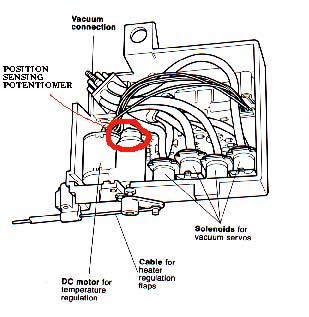 Diagram courtesy of Audi of America When the pot goes open circuit, the op amp/comparator used to monitor this pot voltage "thinks" the lever arm is in the correct position and does not try to run the motor to move the servo arm (cable adjusting air flow). According to my GM contact, GM had a service bulletin that recommended soldering a 680K ohm resistor across two legs (connections) on this position sensing potentiometer. This 680K resistor will ensure there is a voltage difference at the input to the op amp/comparator if this pot goes open circuit which will get the motor turning until the pot wiper contact is reestablished. Here is a diagram showing where the resistor should be soldered on. 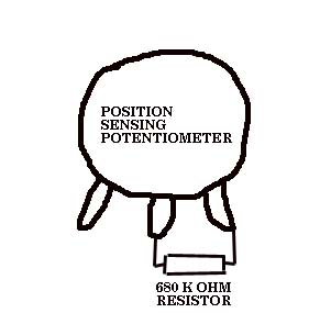 A little contact cleaning spray on the insides of the pot could also help clean up the pot wiper as well. My A/C system temp control finally worked as expected in the 1986 5000T for several years after installing the motor and this resistor mod. The later 200T/Q servo which is mounted on the air box under the plenum cover, may suffer from this same problem, but I have not yet had the servo apart on these later systems. A/C Aspirator Motor for Temp Sensor The Audi 5000, Audi 100/200 and Audi S4/S6 has a A/C Climate Control system that uses a small blower motor or "aspirator" motor to suck air from the passenger compartment (i.e. the area inside the car) across an air temp sensor to help regulate the air temperature inside the car. The intake air temp sensor and aspirator motor are located underneath the padded dash, where the small grill is located in the center of the dashboard. Here is a photo of the Aspirator motor from a 1989 Audi 200. 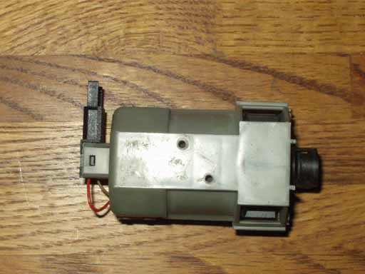
As the car gets above 100k miles, this aspirator motor brushes or commutator can wear out and the motor stops spinning and then it stops sucking air past the air temp sensor. This causes a problem with the climate controls systems ability to accurately regulate the inside air temp. Sometimes these aspirator motors will begin squeaking whenever the A/C Climate control system is turned on in any of the button selections. (ECON, Bi-Level etc.). The motor is usually pretty quiet when it is running, so it can be tough to tell if it is working. One test you can do, is to take a small piece of tissue paper and with the ignition on, and the A/C set to ECON, with the blower speed set to LOW, see if the tissue paper gets sucked against the small grill in the center of the dash area. I have found an alternate source for these aspirator motors, that costs much less than the $250 list price. Here is a photo of the replacement, the electrical connector needs to be changed for use on the Audis. 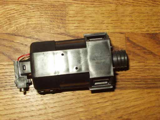
Aspirator motor removal/replacement on the 86-88 5000/T/Q (what a fun job, see below for that info). Here is a photo showing the installation of the aspirator motor looking underneath at the padded dashboard for the 1986-88 5000T/Q. In other words, this photo was taken with the entire dash removed from the vehicle and with the dash assembly turned upside down. The correct way to replace this aspirator motor likely involves removing the dashboard, but I have not tried doing it this way. 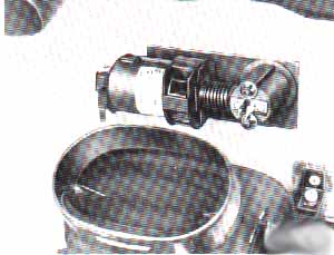 Diagram courtesy of Audi of America Here is the close up diagram showing the clam shell construction of this 5000T/Q aspirator motor and air temp sensor assembly. 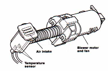 Diagram courtesy of Audi of America 5000T/Q Information: I gained access to the sucker (literally) in the 86 5000T by removing the instrument cluster and the clock/computer switch. The motor is mounted up to the top of the dash and was encased in a plastic clam-shell-like housing that has 4 plastic tangs that had to be un- hitched or un-clipped to allow the lower part of the clam-shell housing to detach and swing down to allow the motor to fall out. As the motor falls out of course all of the carbon brush dust dumps out at well. This plastic clam-shell is riveted to the underneath the padded dash in the 5000T/Q. Getting the motor out initially was a little difficult as you can't see the motor very well. A flashlight and mirror help somewhat just to see what is in there. My aspirator motor had a commutator that was pretty well wiped out. I ended up running the system without the aspirator but moved the temp sensor up closer to the inlet with the hope it would catch a draft now and then. It worked ok but not well as the A/C temp would have a tendency to porpoise up and down. The air temp sensor assembly and housing uses two press on spring clips that are not fun to remove or to re-install, so make sure you really need to remove the air temp sensor, before you tackle it's removal. You should be able to measure the air temp sensor resistance with it installed in the car, not an easy measurement to make, but possible. Aspirator motor replacement on 1989-91 Audi 100/200 I recently parted out a 1989 200T and was stripping the interior when I got a closer look at the installation of the aspirator motor. The aspirator motor housing is mounted with two screws onto a metal bracket along with the Alarm control module and the cruise control module. The bracket is mounted on the front side of the alloy dash mounting frame and isn't easy to see. The bracket must be removed in order to get the 2 screws holding the aspirator motor to this bracket. Here is a photo showing the bracket removed. 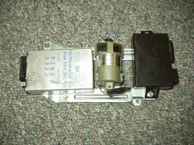 In order to remove this bracket with the aspirator motor and the 2 control units, you need to do the following on 1989-91 Audi 100/200 vehicles equipped with a driverside airbag: First remove the one screw holding the right side dash panel in place. Once you remove the one lower screw on this side panel, the panel should be pulled down to disengage the upper tab, and then pull the panel up and out. Remove the glove box assembly. The glove box has four 4mm allen screws that hold the metal glove box top to the alloy dash mount frame. The two visible allen screws should be removed, and then there are two allen screws that are hidden inside blind holes which only need to be loosened so the glove box will side to the right and drop down. The left side dash cover needs to be removed, it also has one lower screw and needs to be pulled down, and then up and out. The driverside knee bar or lower dash panel needs to be removed to allow getting at the allen screws holding the right side dash wood trim piece. The knee bar is held in place with two hex head screws on the left side behind the side dash panel, one screw underneath the knee bar, and one allen screw below the steering column cover. Once the glove box and the left side knee bar have been removed, you can remove the lower allen screws holding the right side wood trim to the alloy frame. Also remove the two side allen screws holding the wood trim to the alloy frame. Remove the wood trim and you will find an open pocket in the alloy frame and will see the 4 hex head screws holding the metal bracket with the aspirator motor and the 2 control units. Here is a photo showing the pocket area in the alloy frame with the bracket already removed. Note the location of the hex head screws.. 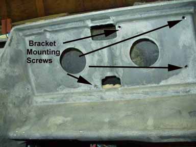 Remove the 4 hex head screws holding the bracket to the allow frame. In order to get the bracket down from behind this alloy frame, you need to first pull down the plastic A/C ducting. There is a hidden screw holding the right end of this plastic duct work to the alloy frame. The hidden screw is located underneath the right side speaker in the dashboard. The speaker grill can be popped up and then slid to the rear to remove. Don't pry on the small defroster duct, only on the rear edge of the speaker grill to pop it up. Remove the one 8 mm nut and remove the speaker. Here is a photo showing the location of the hidden allen screw for the A/C duct. 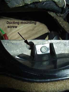 Now you can pull down the plastic A/C ductwork and wrestle down the bracket along with the aspirator motor, the alarm and cruise control modules. You may need to unplug the modules and the aspirator motor to get this bracket down from behind the allow dash frame. The bracket is wedged behind this alloy frame, so getting it down takes a little effort. There will be a rubber hose on the top of the aspirator motor that also needs to be removed as you pull down the bracket. This rubber hose connects the aspirator motor sucking hole to the temp sensor port inlet which is mounted nearby. Dashboard removal on 1989-91 Audi 100/200 The dashboard can be removed after performing the above steps but exclude removing the A/C ductwork and the aspirator motor bracket. Remove the left side wood trim piece, and locate the 3 allen screws holding the padded dashboard to the alloy frame below the rear edge of the padded dash. There is also one screw on each end of the dash underneath the speakers, so remove the left and right speaker grills, the left and right speakers to locate the hidden allen screw in front of the speaker area. There is also one hidden allen screw in the center of the dashboard underneath the center defroster grill. You may need to use a flashlight and mirror to see this hidden allen screw. You don't need to remove the center defroster grill, just a long allen to unscrew the fastener. Once you have the 6 allen screws removed, you can pull up the rear edge of the padded dashboard, and then pull it out toward the rear of the car. There is a spring clip that also retains a tab underneath the dashboard that may require some effort to pop it loose. AC Warm when at idle, Cold when vehicle is moving Here is one possibility regarding an A/C problem where you are not getting sufficient cooling when the car is not moving. This assumes your freon level is ok. Most A/C systems turn on the low speed electric radiator fan when the A/C compressor is engaged. The fan is required to keep air moving over the A/C condenser to allow the hot refrigerant gas coming out of the compressor to have the heat removed from it and convert it to a high pressure liquid. If the radiator fan is not turned on when A/C compressor is engaged, and the car is not moving, the high side pressure will skyrocket and many times there is a high pressure switch that will disconnect the compressors electric clutch when the high side pressure gets to high. When the car is moving there is enough air flow over the condenser to keep the system functioning normally. The 5000/200/100 Audis have a large resistor pack that provides the voltage drop for the low and medium speed radiator fan operation. Sometimes these resistors burn out and prevent low or medium speed operation. AC Clutch/Pulley replacement, belt squealing or burned up? If the A/C compressor pulley bearing has gone south and has partially seized up, this would explain the belt squealing/burning up etc. The other possibility would be the compressors internal crank/pistons blew up (grenaded) (belt squealing/burning with the A/C clutch engaged). Is the front face (outer portion) of the compressor clutch plate stuck or welded to the pulley clutch face? If it is not stuck or welded to the pulley and if the outer face of the A/C clutch still rotates freely by hand (A/C magnetic clutch turned off) then the internal guts of the compressor "could" be ok. If the pulley bearing is causing the clunk when you spin the pulley with the belt removed then the bearing can be replaced. On the Nippon Denso Compressors, the front face of the compressor clutch can be pulled off after removing the nut and lock washer. Note there is a woodruff keyway on the compressor shaft and some washers that are used to space out the clutch face correctly. Normally you need a special screw in puller to get the front clutch face off but in some cases I have just pulled off the outer clutch face by hand. After removing the outer clutch face, the snap ring can be removed so the pulley assembly can be pulled off. Then the pulley bearing can be pressed out or driven out. The bearing number can be read off the original pulley bearing and any bearing supply house should have a replacement. If the A/C compressor internal guts grenaded then you may have metal fragments/gray crud inside the whole A/C system. This is very bad! No Duh! You may need the whole system taken apart and flushed, it can be very difficult to get this fine metal slurry out of the system if the compressor ran for awhile as it blew up. If you are not successful getting the metal fragments out you will be replacing compressors and other parts on a regular basis. Make sure the Restrictor screen tube is removed from the inlet pipe on the Evaporator coil and replaced, as these can catch some of the metal fragments. It is also a good idea to replace the receiver/dryer canister when replacing the compressor. AC Compressor Replacement, Evaporator Restrictor Replacement As mentioned, the A/C system in the 1986-88 5000/T/Q and 1989-91 100/200T/Q is a system derived from the Harrison CCOT system used in General Motors cars, Cadillac etc. CCOT stands for Cycling Clutch Orifice Tube, because the system uses a simple Orifice Restrictor Tube (with screen) to regulate the flow of liquid freon into the evaporator housing where it expands into freon gas, absorbs heat and gets sucked back into the compressor. The A/C compressor is cycled on and off from a electrical thermostat as necessary to regulate the temperature of the evaporator coils to prevent freeze up. If you are replacing the compressor for any reason, after the system is discharged, and the Freon is recovered, you should have the repair shop remove the existing Orifice Restrictor Tube (with screen) and inspect it for any foreign metal or other gunk. Very often this step is overlooked, and this Restrictor Tube gets plugged up with metal gunk and will not allow normal flow of liquid freon into the evaporator. This Orifice Restrictor Tube is located inside the metal pipe, just inside the pipe at the fitting where the high pressure aluminum line connects to the copper line on the evaporator housing. A pair of needle nose pliers can be used to pull out the Restrictor tube/screen assembly. If you have trouble getting the tube out, several tool manufacturers (Mac Tools, Snap On, etc) make extraction tools to remove the orifice tube from the GM and Ford Systems which use this same Restrictor Tube setup. A/C Compressor Manifold Seal and O rings The 1986-88 Audi 5000 (after VIN 44-G-053401) and 1989-91 Audi 100/200 use the Nippon Denso 10P17C A/C compressor which has a separate hose manifold. Some of these hose manifolds are 2 piece and have a rubber seal between the 2 halves. Audi does not list this seal separately, nor does it list the 4 O rings between the A/C compressor and the manifold. Thanks to a fellow Audi fan, there is an A/C company "Polar Bear" who sells this manifold seal (part number GA1446) and the O rings (part number OR 11160) between the compressor and manifold. No air from the center vents? Fogging Windows? A/C Recirculation Door, Broken Return Spring or Vacuum Servo Mount? There are two air control doors that control the air flow into the evaporator housing, one lower door inside the vehicle under the passenger side dash, (behind the glove box) and one upper door under the plenum cover under the hood. These two doors are connected together with a hinge, so that if the upper door is open fully, the lower door will be closed fully and vice-versa. These two doors control the amount of fresh air that enters the Air Conditioning system and also allow the system to operate in Recirculation mode when the upper door is closed and the lower door is open. Many times when the windows are fogging up on the inside of the vehicle, the vacuum servo that pulls the upper door closed, breaks loose from its plastic cross bar mounting. In other cases the lower door return spring breaks or the upper spring mount cross piece (plastic) breaks and the spring comes loose which prevents the lower door to be closed. Because the upper and lower doors are hinged together, when the lower door is open, it does not open the upper door to allow fresh air into the vehicle. (replacement spring part number 443-271-241). In some cases you can reuse the spring if the end has broken off, by bending the end into a hook and reattaching the upper end over the plastic cross piece which is part of the evaporator housing, and is located just below the servo mounting area. To inspect the servo mount and the return spring for breakage, remove the two screws holding the passenger side lower dash trim piece (black plastic piece with square holes and interior light mounting). Then locate the inside fresh air door, you can open the glove box door to get a better view. The fresh air door can then be pulled open towards you with your hand and you can look inside to check for a broken servo mount and check for a broken spring. Usually when the return spring is broken, the fresh air door will already be hanging open a little. Often times leaves and other debris will be on the bottom of the evaporator housing. While you are in there checking the servo mount and the return spring, you can look up and see the evaporator coil fins inside this housing and clean out any foreign matter. This lower door can be taken off completely by removing the two Phillips screws which are under the sound deadening material. You can also look at the upper recirculation door by removing the right side wiper blade and the plastic plenum cover under the hood. The upper recirculation door is in back of the evaporator housing. There are two Phillips screws that can be removed on the upper door to get a better view of the repair. The servo uses a twist lock flange to connect to the upper door. There is a repair kit for the broken vacuum servo mount, which consists of a U shaped metal bracket that is screwed in place with self tapping screws. Audi part number is 200-271-200. I used a 3/8 drive air ratchet from inside the car to drive in the self tapping screws, a 1/4 drive air ratchet or right angle screw driver would also work. It is very tight working inside the evaporator housing, so getting this metal U bracket mounted is a little tricky. NOTE: Use caution when working inside the evaporator housing, as you could punch a hole in the evaporator housing coils which are behind the exposed fins. The A/C system has freon under pressure inside these coils. OTHER RETURN SPRING AND LOWER DOOR NOTES: The lower door has a removable plastic lug piece in the center that the lower end of return spring connects to. You can remove this plastic piece by turning it counter clockwise and pulling it out. The spring can then be connected to the upper plastic cross piece just below the servo mount area, and the lower end of the spring can be inserted into the hole in this plastic lug piece. Then you can stretch the spring and reinsert the plastic lug piece into the lower door. The spring tension if very high, so it is a little tricky doing this. Note: In some cases the upper plastic cross piece spring mount can break, requiring that you make or drill another upper spring mount hole, somewhere in this plastic cross piece below the servo mount. Audi issued a service bulletin on this problem. They noted that the rubber door seals often cause the problem when they stick to the evaporator housing and make opening the doors difficult for the servo. The part number for replacement door seals is 433-271-263A. Make sure you remove any left over adhesive from the door seal area to prevent future problems. Here is a picture of the servo the upper and lower door and the return spring. 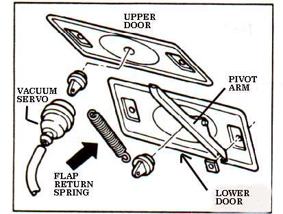 Diagram courtesy of Audi of America In addition to the servo breaking loose, often times the vacuum hose to the servo falls off and creates a vacuum leak. This type of vacuum leak will often prevent the air from coming out of the center vents correctly. NOTE: On the 1986-88 5000 there is also a small vacuum hose connection inside the engine compartment for the A/C system that should be checked. The small hose connection is somewhat hidden, as it is down below the Brake master cylinder area, near the frame rail. This small 3mm black plastic vacuum line for the A/C has a short piece of 6mm rubber hose where it connects to the 8mm diameter hard plastic pipe coming off the hose from the intake manifold with the check valve. The hard plastic pipe is routed down near the frame rail, where the small A/C hose connects, then the 8mm plastic pipe is routed over towards the fender, and then up and back to the vacuum reservoir behind the left front fender. The later 1989-90 200T/Q has this small vacuum connection (3mm black plastic line) at the check valve just below the ignition distributor and is easier to check. References: Audi of America service training publication: "The New Audi 5000, Introductory Service Information "Digital Climate Control for the 1986 Audi 5000" Copyright © SJM Autotechnik™ , all rights reserved Return to Troubleshooting Tips page. Return to SJM Autotechnik™ main page. |
| About Us Privacy Policy Terms of Use Links Customer Service Safety Information Home |