|
ECU Fault Code Retrieval, ECU Output Tests 10 Valve 5 Cylinder Turbo Engine 1986-88 Audi 5000 Turbo and Audi 5000 Turbo Quattro, UK ur-quattro with MB Engine 1989-91 Audi 200 Turbo 1989-90 200 Audi Turbo Quattro
The 1986-91 Audi I5 Turbo engines have Engine Control Units equipped with a "self-diagnostic system". This system can test 13 input and 5 output system checks on the 1986-88 5000TQ and early 1989 200TQ. It will perform 17 input checks and 6 output system checks on the later dual knock sensor MC engine in the 1989-90 200TQ and 1989-91 200T. The 1991 200TQ vehicles with the 20V engine and Motronic Engine Control Unit can record 31 faults and perform 8 output checks. Anytime an engine problem is occurring, this Fault Code system should be used to first locate any system fault codes that have been recorded [3]. If the vehicle starts and runs: You should drive the car for a minimum of 5-10 minutes and raise the engine speed above 3000 RPM and ensure that the manifold pressure goes above 1.2 bar. You want the engine coolant temp to get above 80C, (176F). You should accelerate at full throttle in 3rd gear to exercise this diagnostic system correctly. NO START CONDITION: Crank the engine with the starter for at least 5 seconds and make sure you leave the ignition on after cranking the engine during the no start condition. NOTE: On the 1986-88 5000T/Q and early 1989 200T/Q, the ignition should not be turned off after doing this full throttle test road test or after the "No Start" cranking test is done, as the fault memory will be erased. After doing the road test or the "No Start" cranking test, proceed to the section below for reading any fault codes stored during this process. Fault Code Reading: 1986-88 5000 Turbo and Turbo Quattro, Early 1989 200 Turbo and Turbo Quattro, UK based ur-Quattro with MB engine This system uses the "Check Engine" light in the instrument cluster to indicate faults in the system during the fault code reading process. 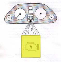 Diagram courtesy of Audi of America This light is also referred to as the Electronic Ignition Warning Light in the owners manual.
ROAD TEST After conducting a road test for 5-10 minutes, where the engine is warmed up and the engine is run briefly at full throttle in 3rd gear above 3000 RPM with boost going above 1.0 bar, LEAVE THE ENGINE IDLING as the fault codes will be erased if the engine is shut off after the road test. NO START CONDITIONS: If the car will not start, but will crank over, you can check for any fault codes stored. Crank the engine for at least 5 seconds and then leave the ignition on. The procedure below can also be used for retrieving fault codes under no start conditions. To start the fault code reading sequence, Insert a spare fuse into the top of the fuel pump relay for four seconds and then remove the fuse. This starts the fault code sequence by bridging the contacts on the top of the fuel pump relay. These fuel pump relay fuse contacts are connected to pin 31 on the ECU and to ground. The Fuel Pump relay is located under the hood in the main fuse panel near the windshield on the drivers side. See illustration below:  Diagram courtesy of Audi of America The "Check Engine" warning light should come on whenever the fuse is inserted into the top of the fuel pump relay. UNDER NORMAL DRIVING CONDITIONS THERE SHOULD NOT BE A FUSE INSERTED ON TOP OF THE FUEL PUMP RELAY. THIS FUSE IS ONLY INSERTED "TEMPORARILY" INTO THE TOP OF THE FUEL PUMP RELAY TO ACTIVATE THE FAULT CODES OR TO RUN THE OUTPUT TESTS. There should not be a fuse "permanently" installed in these contacts on top of the fuel pump relay. NOTE:The fault code reading procedure will be canceled if the engine RPM is raised above 2000 or if the ignition is turned off. Each fault code consists of four groups of pulses. The exact sequence for each code is a start sequence of 2.5 seconds with the lamp on, and 2.5 seconds pause with it off. The codes then follow as a half-second pulse with the light on, separated by a half-second pause with the light off, with a larger pause of 2.5 seconds between each set of pulses. Example:If no fault codes are stored, code 4444 will be displayed by the ECU. The ECU will turn the "Check Engine" light on and off as follows after the fuse is inserted into the fuel pump relay for 4 seconds and then removed. Light on (2.5 sec), Light off (2.5 sec) Now here comes the code 4444 Blink, pause, Blink, pause, Blink, pause, Blink, (2.5 second pause) Blink, pause, Blink, pause, Blink, pause, Blink, (2.5 second pause) Blink, pause, Blink, pause, Blink, pause, Blink, (2.5 second pause) Blink, pause, Blink, pause, Blink, pause, Blink, (2.5 second pause) Code 2322 (air temperature sensor) would be displayed as follows: 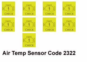
In other words..... Blink, pause, Blink, (2.5 second pause) Blink, pause, Blink, pause, Blink, (2.5 second pause) Blink, pause, Blink, (2.5 second pause) Blink, pause, Blink, (2.5 second pause) The sequence of displayed pulses will keep repeating until the system is stepped to the next fault code stored (if any) by bridging the contacts on the fuel pump relay again for 4 seconds. The lamp will blink "once" at 2.5 second intervals to indicate that the last error code has been read. Use a note pad to write down the fault codes as they are displayed and then check for the specific fault code description listed in the section below. Check the Bentley Manual for additional information. Output Tests: 1986-88 5000 Turbo and Turbo Quattro, Early 1989 200 Turbo and Turbo Quattro UK based ur-Quattro with MB engine There is also an ECU controlled "output test" mode that allows you to run the fuel pump and the other ECU controlled solenoids to verify correct ECU/solenoid/wiring operation [3]. This output test begins by turning on the fuel pump and then you can step through subsequent output tests where it will cycle each electrical solenoid on and off in a particular order. The Check Engine light should flash during the Output tests to indicate which component/solenoid is being tested. Some later vehicles use fuse #28 in the main fuse box to supply +12V to all of these solenoids, so this fuse should be checked if they are not operating. On the US based MC engine vehicles, you can activate the Output Tests two ways, the first way is to insert a spare fuse into the top of the fuel pump relay and then turn on the ignition (Do not crank or start the engine). The fuel pump will begin to run to indicate the start of the output tests. Now remove this spare fuse and insert it again into the top of the fuel pump relay for 4 seconds to step to the next output test. UNDER NORMAL DRIVING CONDITIONS THERE SHOULD NOT BE A FUSE INSERTED ON TOP OF THE FUEL PUMP RELAY. THIS FUSE IS ONLY INSERTED "TEMPORARILY" INTO THE TOP OF THE FUEL PUMP RELAY TO ACTIVATE THE FAULT CODES OR TO RUN THE OUTPUT TESTS. See illustration below for location of the fuel pump relay which is under the hood in the main fuse panel near the windshield: Diagram courtesy of Audi of America The second way to start the Output tests is to first turn on the ignition and "then" insert the fuse into the top of the fuel pump relay for 4 seconds, as mentioned, the fuel pump will begin to run "until" the fuse is removed and inserted for another 4 seconds, which will cause the ECU to step to the next output test. Note: MB ENGINE: The UK based ur-Quattro with the MB engine, will not start the output tests if you turn on the ignition and THEN insert the fuse. You MUST first insert the fuse and THEN turn on the ignition with these vehicles. Each solenoid tested during the output test should make an audible clicking noise when it is turned on and off by the ECU during these output tests. You can also place your hand on the solenoid to verify whether it is being turned on during these tests. Here is the sequence of the Output Tests:
Fault Code Reading
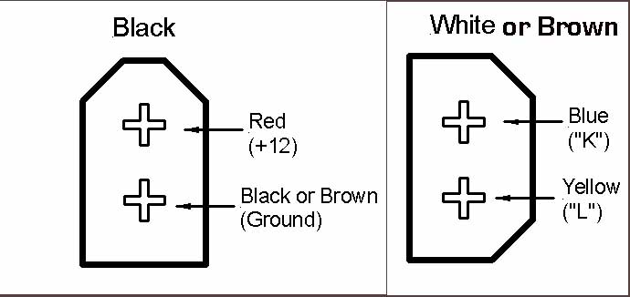
If you have a Palm Device diagnostic cable and software, or a PC diagnostic cable and software with OBD-II cable connector, you will need to use the VAS5051/2 cable adaptor to connect to these black and brown diagnostic connectors.
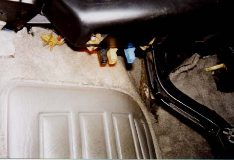
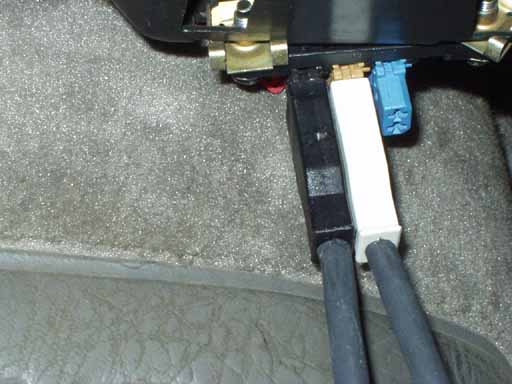
Using Check Engine Light to Blink out the codes: These three connectors are used to access the diagnostic capabilities inside the Engine Control Unit IF you are using the LED to blink out the codes. The fault codes can also be blinked out by using a jumper wire connected for 4 seconds across the diagnostic connectors. See details below for this procedure. The "Check" engine light in the instrument panel or a separate light bulb or LED is used to flash out the fault codes.  Diagram courtesy of Audi of America IMPORTANT DETAILS: This yellow "Check" engine light will normally come on when the ignition is turned on "if" the bulb is installed in the dash. The operators manual refers to this "Check" engine light as the "Emission Control System (ECS) malfunction Indicator Light." Some of the 200TQ's have no "check" engine light bulb installed in the dashboard assembly even though the circuitry is there. Normally this bulb is installed in-between the "Airbag" light and the "Door Open" warning light on the right side of the dash and as mentioned, this light should come on when the ignition key is first turned on. You can partially pull the dash console out on the right side and reach around and install this "Check" Engine light bulb. Use one of the Osram 2721 light bulbs, 12 volt, 1.2 Watt that push into place. If you do not have the light bulb installed in the dash, you will need to connect an LED or low wattage light bulb (12 volt, 1.2 Watt) across these diagnostic connectors in order for the ECU to blink this light so you can read out the fault codes. Vehicles produced for sale in California should have this "Check" Engine light bulb installed in the dash. Details on building the LED fault code light can be found at the bottom of this page. A short jumper wire is also required to initiate the diagnostic sequence. Each diagnostic connector has two terminals in it. They are arranged as follows: These vehicles may have fuel pump relays which have the 2 terminal connections at the top of the relay. These contacts were used on older Audis to initiate the fault code sequence by inserting a fuse into the top of the fuel pump relay for four seconds. This procedure may also work on the Audis which have the colored fault code connectors under the dashboard. There SHOULD NOT be a fuse permanently installed in top of these fuel pump relays, as it may prevent the normal retrieval of the fault codes. Black, Brown and Blue Connectors Used to "Blink" out the Codes with LED 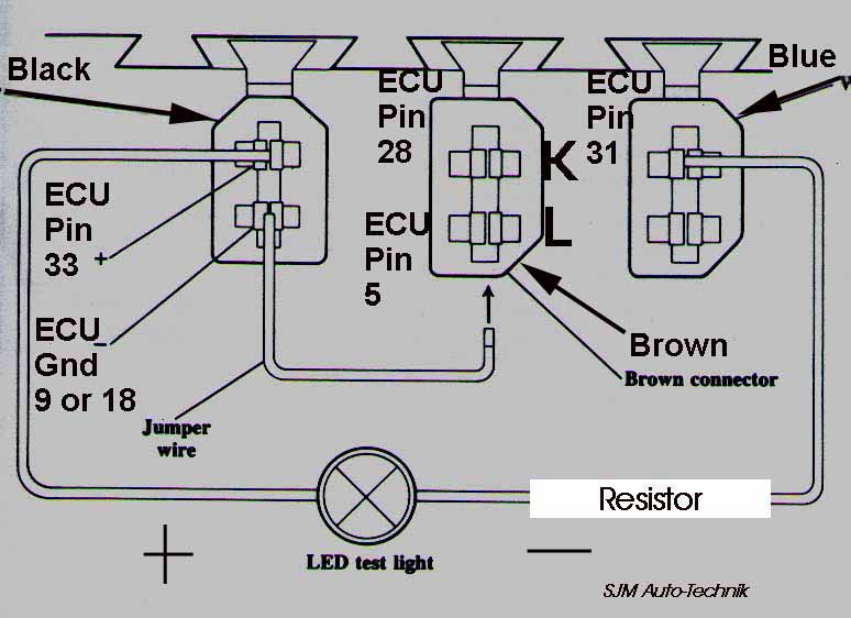 Diagram courtesy of Audi of America NOTE: SOMETIMES THE POSITION AND LOCATION OF THESE CONNECTORS HAS BEEN CHANGED, SO CHECK THE COLOR OF THE CONNECTOR MAC14 ECU: The Black Connector has +12V and Ground, the top terminal has +12V which is connected to the ECU pin 33, the lower terminal in the black connector is connected to ECU ground, pin 9 or 18. The brown connector has the top terminal connected to ECU pin 28, the lower terminal is connected to ECU pin 5. The blue connector top terminal is connected to ECU pin 31. As mentioned, with the engine idling, you activate the fault code system by connecting the jumper wire across the two terminals for four seconds and then remove the jumper, the ECU will then begin the sequence to blink out the fault codes via the instrument panel "Check Engine" light or by flashing the LED connected across the diagnostic connectors. AUDI Diagnostic Harness 357 971 514E If you have the "Check Engine" light bulb installed, there was an Audi made diagnostic harness with black and white diagnostic connectors that was included with some new Audi vehicles many years ago. Audi part number 357 971 514E. This can be used to plug into the diagnostic connectors which acts like a jumper wire to blink out the fault codes. Unfortunately, this little diagnostic harness is no longer available. 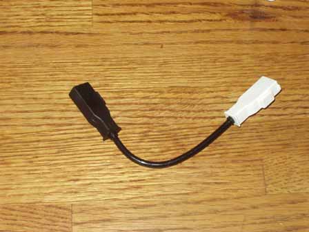 Audi Diagnostic Harness 357 971 514E ADDITIONAL FAULT CODE INFO: NOTE: If the ignition is turned on, but the engine is NOT running and you check the fault codes, you may get a "false" code 2111 or 2112 (RPM and TDC sensors) because the engine is not turning. NOTE: The fault code reading procedure will be canceled if the engine RPM is raised above 2000 on the MC 10V engines or if the ignition is turned off for all models . Each fault code consists of four groups of pulses. The exact sequence for each code is a start sequence of 2.5 seconds with the lamp on, and 2.5 seconds pause with it off. The codes then follow as a half-second pulse with the LED light on, separated by a half-second pause with the LED light off, with a larger pause of 2.5 seconds between each set of pulses. Example:If no fault codes are stored, code 4444 will be displayed by the ECU flashing the LED. The ECU will flash the LED on and off as follows after the jumper wire is inserted into the connectors for 4 seconds and then removed. LED on (2.5 sec), LED off (2.5 sec) Now here comes the code 4444 Blink, pause, Blink, pause, Blink, pause, Blink, (2.5 second pause) Blink, pause, Blink, pause, Blink, pause, Blink, (2.5 second pause) Blink, pause, Blink, pause, Blink, pause, Blink, (2.5 second pause) Blink, pause, Blink, pause, Blink, pause, Blink, (2.5 second pause) 2322 (Air Temperature sensor) would be displayed as follows: In other words..... Blink, pause, Blink, (2.5 second pause) Blink, pause, Blink, pause, Blink, (2.5 second pause) Blink, pause, Blink, (2.5 second pause) Blink, pause, Blink, (2.5 second pause) The sequence of displayed pulses will repeat until the system is stepped to the next fault code stored (if any) by connecting the jumper wire across the connectors again for 4 seconds. The LED will blink once at 2.5 second intervals to indicate that the last error code has been read. Use a note pad to write down the fault codes as they are displayed and then check for the specific fault code description listed in the section below. Check the Bentley Manual for additional information. In my 1989 200TQ, I have permanently connected a momentary push button switch across the two jumper wire connections so that I only need to push this button to activate the fault codes. I ended up installing the "check" engine light bulb back in the dash to avoid having to use the LED connected under the dash. NOTE: If you connect an LED permanently across these diagnostic connectors, you will notice that the LED "glows" dimly all the time even with the ignition off. The LED glows dimly because a very small current is flowing from the ECU through the LED to the +12V supply when the LED is connected to the diagnostic connectors. This current flow is only 0.4 milli amps, (400 micro-amps), or stated another way, 0.0004 amps. It is probably better to install the Dash mounted "Check" Engine light bulb than to permanently connect the LED across the diagnostic connectors. NOTE: In some cases, on these later 1989-90 200TQ vehicles, if the "Check" Engine light bulb "is" installed in the dashboard, then inserting a spare fuse into the fuel pump relay fuse slot "may" initiate the fault code reading sequence as was done in the 1986-88 5000TQ vehicles. Some of the later 200TQ's may have a slightly different fuel pump relay which no longer has the fuse contacts installed. OTHER DETAILS: Fuse #21 supplies power to Pin 33 on the MAC14 ECU for maintaining the fault code memory. This fuse also supplies the +12V for the black fault code connector underneath the dash. Check this fuse #21, if the fault codes do not blink out using the LED. Fuse #28 supplies +12V to the CIS frequency valve, the Charcoal canister solenoid, the Waste Gate solenoid, the charcoal filter cut off valve. Check this fuse if these components are not operating correctly. FAULT CODE ERASING NOTE: You can remove fuse #21 for a few minutes to erase any stored fault codes in these vehicles. If you conduct the OUTPUT tests, the fault code memory will also be erased at the end of the procedure. NOTE: Fuse 28 is located under the hood in the fuse box on the "side" rail of the fuse panel perpendicular to the other fuses. These fuses on the side rail are NOT Spare fuses! The fuse may be underneath a small red cover with Motor - Moteur on top. Output Tests 1989-90 200 Turbo Quattro, 1989-91 200 Turbo There is also an "output test" mode that will enable the MAC14 ECU to turn the fuel pump on and also cycle the engine electrical solenoids on and off to verify they are working correctly [3]. Fuse #28 supplies +12V to the ECU controlled solenoids, so check this fuse if they do not operate. To activate the Output Tests, you must first connect the jumper wire to short across the Fault Code Connectors as shown and THEN turn on the ignition to start the output tests. Yo can also connect the LED to read out the Output test codes.
(1989-91 200TQ/100) The LED with a series resistor is normally connected across two terminals on the fault code connectors. The LED normally needs a resistor in series to limit the current, most LED's operate with 10-30 milli-amps (0.010 to 0.030 amps). A 1/4 watt 680 ohm resistor works pretty well but you don't have to use a resistor with exactly 680 ohms. The current that is flowing through the LED test light circuit is calculated as follows: Charging system voltage minus voltage drop across LED, divided by the resistance (14 Volts - 1.2 Volts)/680 = 18.8 milli-amps (0.0188 amps). The lower the value of resistance, the more current that flows and the brighter the LED, up until the point the smoke gets out. Radio Shack should have the necessary components to build this LED test light. There are some newer "Super bright" LED's that some electronic supply houses carry that should work great in this application. A Low Voltage LED Test Light can be made for testing voltages from 2.5V to 5.0V by using a lower value resistor, a 120 ohm resistor will provide ~10 to 30ma through the LED when testing voltages from 2.5V to 5.0V. Here is a diagram that illustrates the connection of the resistor in series with the LED. 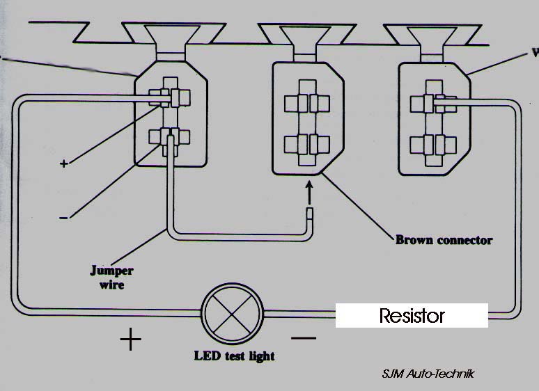 Diagram courtesy of Audi of America I normally use two different colored. wires (black/red) as the LED is polarity sensitive, the flat section on the LED lamp is normally the negative connection. Bolt lug terminals (U shaped) with one leg trimmed off, can be crimped on the wire ends to allow easy insertion into the fault code connector terminals. It won't hurt it if you connect the LED backwards, it just won't make any light.....the resistor can be connected in series on either the + or - wire to the LED. References: [3] Audi of America, Technical service training publications: "1986 Model Change Information" "1989 Model Change Information" All rights reserved. Copyright © SJM Autotechnik™ , all rights reserved Return to Troubleshooting Tips page. Return to SJM Autotechnik™ main page. |
| About Us Privacy Policy Terms of Use Links Customer Service Safety Information Home |
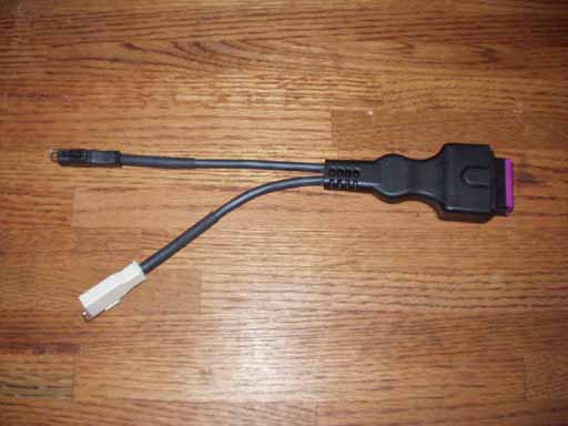 VAS5051/2 cable adaptor