|
Audi V8 Motronic ECU Fault Code Retrieval, ECU Output Tests Automatic Transmission Fault Code Retrieval, Output Tests Instrument Cluster Fault Code and Output Tests 1990-91 Audi V8 with 3.6 litre PT Engine 1992-94 Audi V8 with 4.2 litre ABH Engine
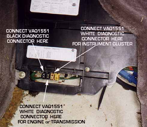
Introduction: Engine Control Unit (ECU) Fault Code System The 1990-94 Audi V8 engines have Motronic Engine Control Units (ECU) equipped with a "self-diagnostic system" [7]. The Engine Control Unit can record 29-31 faults and perform 10 output checks. (12 on the ABH engine) Anytime an engine problem is occurring, this Fault Code system should be used to first locate any system fault codes that have been recorded. PLEASE NOTE: Mechanical Engine problems can also create fault codes and poor running conditions, so make sure the engines valve system and timing belt drive are correct, as well as checking the engine leak down for problems in the piston rings, or valves. The V8 fuel pressure regulator may have a ruptured diaphragm which can cause rich running when the fuel is sucked into the engine vacuum port. In extreme cases the engine can hydro lock due to the excessive fuel being ingested into the cylinders and can cause major engine damage to the rods, and/or stripped flywheel teeth when trying to start a flooded engine. Poor engine or chassis grounds can also cause a host of fault codes to be generated, always check the integrity of the ECU grounds on the engine, as well as the main engine ground from the chassis to the block. If the vehicle starts:You should drive the car for a minimum of 5-10 minutes and raise the engine speed above 3000 RPM. You want the engine coolant temp to get above 80C, (176F). Verify fuses 4, 5, 13, 23, 24, and 27 are OK If the vehicle does not start: Crank the engine with the starter for at least 15 seconds and then leave the ignition on after cranking and check for any stored faults. After doing the road test or the "No Start" cranking test, proceed to the section below for reading any fault codes stored during this process. 1990-91 Audi V8 with 3.6 litre PT Engine and for 1992-94 Audi V8 with 4.2 litre ABH Engine The Motronic ECU has a non volatile memory for the fault codes that can be read later even if the car has been turned off after the road test. There should be four (4) connectors grouped together underneath the passenger side carpet area (USA Left Hand drive), From left to right, they should be arranged as follows: First one on the left is black, then another black, then one brown and finally one yellow connector.
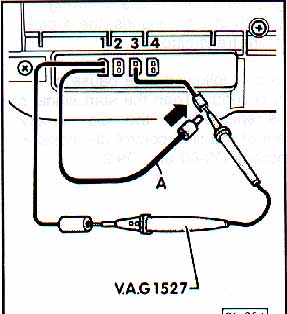
These connectors are used to access the diagnostic capabilities inside the ECU (Engine Control Unit), the automatic transmission, and from the Instrument Cluster. Engine or Transmission Fault Code Diagnosis: This is done with the engine running or the ignition key on using the factory VAG1551, or VAG1552 scan tool connected to the first two black connectors. If you have the Ross-Tech VAG-COM PC Interface and Software you need to get the VAS5051/2 adapter that you will use to also connect to the first two black connectors. The VAG1551, VAG1552 or VAS5051/2 black diagnostic connector plugs into the LEFT black connector as shown above. The White diagnostic connector on the VAG1551, VAG1552 or VAS5051/2 plugs into the second black connector, or phrased another way, the black connector located on the right side. BEFORE PLUGGING INTO THESE DIAGNOSTIC CONNECTORS, YOU SHOULD FIRST VERIFY THAT THE FIRST BLACK CONNECTOR ON THE LEFT HAS +12V and GROUND AS SHOWN
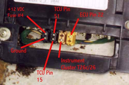
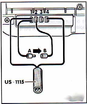
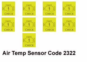
You can also blink out the fault codes by using a jumper wire connected across the fault code connectors along with an LED Test light (US 1115 equivalent) as shown here. Diagrams courtesy of Audi of America The "Check" engine light in the instrument panel (dashboard) will blink out the fault codes on the California vehicles, or by using the LED test light (US 1115 or equivalent) as shown in the above diagram. See section below if you don't get the LED or "Check Engine" light to blink out the codes. If the "Check" engine light does not come on with the ignition key turned to the on position, then you may not have a bulb installed in the instrument panel. If this is the case, you "may" be able to install a 1.2 Watt instrument panel light bulb with twist lock socket or as already mentioned, use an LED connected across the fault code connectors to blink out the fault codes. As mentioned, with the ignition key on or with the engine idling, you activate the fault code system by connecting the jumper wire across the two terminals for four seconds and then remove the jumper, the ECU will then begin the sequence to blink out the fault codes. In some cases if the ignition is on, but the engine is not running you may get a 2111 or 2112 (RPM and TDC sensors) fault code or 2234 (supply Voltage) fault code. NOTE: The fault code reading procedure will be canceled if the ignition is turned off. Problems? No Fault code Light blinking? Engine Control Unit (ECU) or Transmission Control Unit (TCU) does not blink out the fault Codes Some vehicles may have fuel pump relays which have the 2 terminal connections at the top of the relay. These contacts were used on older Audis to initiate the fault code sequence by inserting a fuse into the top of the fuel pump relay for four seconds. There SHOULD NOT be a fuse permanently installed in top of these fuel pump relays, as it may prevent the normal retrieval of the fault codes. You may need to check the fuse or do some wiring trouble-shooting if the ECU or TCU does not blink out the codes. Fuse #4 supplies +12VDC power to the top terminal in the 1st BLACK diagnostic connector on the left. The lower terminal in this 1st BLACK diagnostic connector should be ground. Use a test light to verify the first diagnostic connector supplies +12V and Ground. The 2nd BLACK diagnostic connector top terminal connects to the Transmission Control Unit (TCU) pin number 51 and Engine Control Unit (ECU) pin 55. The 2nd BLACK diagnostic connector lower terminal is connected to the Transmission Control Unit (TCU) pin number 15 and ECU pin 13. If you are having trouble reading fault codes or communicating with the ECU or TCU, you may want to use an Digital Multi-Meter (DMM) resistance measurement to verify a good connection between the diagnostic connector terminals and the Transmission Control Unit (TCU) and ECU after unplugging the main connector at the TCU and ECU. The 3rd BROWN diagnostic connector top terminal is not used. The 3rd BROWN diagnostic connector lower terminal is connected to the instrument cluster connector T26c, terminal 26. Use an Digital Multi-Meter (DMM) resistance measurement to verify a good low resistance connection between the diagnostic connector terminal and the instrument cluster connector T26c/26. The 4th YELLOW diagnostic connector top terminal is connected to the Engine Control Unit (ECU) terminal 22. Use an Digital Multi-Meter (DMM) resistance measurement to verify a good low resistance connection between the diagnostic connector terminal and the Engine Control Unit (ECU) terminal 22 after unplugging the main connector at the ECU. FAULT CODE DESCRIPTION Blink Blink goes the light...... Each fault code consists of four groups of pulses. The exact sequence for each code is a start sequence of 2.5 seconds with the lamp on, and 2.5 seconds pause with it off. The codes then follow as a half-second pulse with the LED light on, separated by a half-second pause with the LED light off, with a larger pause of 2.5 seconds between each set of pulses. Example:If no fault codes are stored, code 4444 will be displayed by the ECU flashing the LED. The ECU will flash the LED on and off as follows after the jumper wire is inserted into the connectors for 4 seconds and then removed. LED on (2.5 sec), LED off (2.5 sec) Now here comes the code 4444 Blink, pause, Blink, pause, Blink, pause, Blink, (2.5 second pause) Blink, pause, Blink, pause, Blink, pause, Blink, (2.5 second pause) Blink, pause, Blink, pause, Blink, pause, Blink, (2.5 second pause) Blink, pause, Blink, pause, Blink, pause, Blink, (2.5 second pause) Code 2322 (Air Temp sensor) would be displayed as follows: In other words..... Blink, pause, Blink, (2.5 second pause) Blink, pause, Blink, pause, Blink, (2.5 second pause) Blink, pause, Blink, (2.5 second pause) Blink, pause, Blink, (2.5 second pause) The sequence of displayed pulses will repeat until the system is stepped to the next fault code stored (if any) by connecting the jumper wire across the connectors again for 4 seconds. The LED or "Check Engine Light" will blink once at 2.5 second intervals to indicate that the last error code has been read and that code 0000 is being displayed. Use a note pad to write down the fault codes as they are displayed and then check for the specific fault code description listed in the section below. Check the Bentley Manual for additional information. If vehicle is equipped with an Automatic Transmission, the Transmission fault codes can now be read using the PRND321 display light. See Section Below for more details. Automatic Transmission Fault Code Reading 1990-91 Audi V8 3.6 litre PT Engine and for 1992-94 Audi V8 with 4.2 litre Engine [7] The Automatic Transmission uses a control unit that controls shifting operation, and this Transmission control unit communicates directly with the Engine Control Unit (ECU). Both the ECU and the Transmission Control Unit can store fault codes if there is a problem detected with some of the electrical components. The Transmission may go into "Limp Home" mode if certain components are not working correctly. If the Transmission goes into "Limp Home" mode, all the PRND321 indicators will be lit up, and the transmission will stay in 4th or 3rd gear. In order to blink out the Transmission Control Unit fault codes, you must first blink out the Engine Control Unit fault codes. In other words, you need to connect the jumper wire for 4 seconds, then remove to read out a code, then connect again for 4 seconds, then remove and read out the next code as many times as required until you get to the end of the ECU fault code testing sequence. The end of the fault code sequence is indicated by the 0000 code which is shown by the Check Engine Light or LED test light blinking on/off every 2.5 seconds. With the ignition key still on, then connect the jumper again for 4 seconds to start the Automatic Transmission fault code process. The fault codes will be blinked out on the PRND321 Display in the instrument cluster. The fault code output from the PRND321 display uses the same convention as the ECU fault code blink code output. In other words, connect the jumper wire across the appropriate two terminals for 4 seconds, then remove to flash out the fault codes. Repeat until 0000 code is displayed.
Diagram courtesy of Audi of America A list of AUTOMATIC TRANSMISSION fault codes is at the bottom of this page. Make sure fuse #29 is ok, as I believe it supplies +12V to the Transmission Control Unit. NOTE: The Micro-Fiche Repair Manual for the 1990-92 Audi V8 does not list whether the Fault codes can be blinked out using the LED for either the 1990-91 Audi V8 with 3.6 litre or for the 1992 V8 with 4.2 litre Engine, BUT the factory manual for the 1990 V8 with 3.6 litre engine DOES show the fault codes can be blinked out and I have done this on the 1990 Audi V8. I assume this can be done on the later 1992-94 V8 with 4.2 litre Engine as it uses the same transmission, but I have not verified this. If the area around all selector positions (PRND321 display) remains lit, See the fault code listings for fault codes 1111 OR 1314. Flash code 4444 means there are no stored fault codes for the Automatic Transmission. Erasing Fault Codes, ECU Fuses: 1990 Audi V8 Engine Fuse #27 "supposedly" supplies power to the Motronic ECU for maintaining the fault code memory. You "should" be able to remove this fuse #27 for a minute or so to erase any stored fault codes, BUT I have not verified this. This will also erase any adaptive fuel mixture values stored in the ECU. The ECU will relearn these values after the car has been driven. You can also erase any stored fault codes by running the OUTPUT tests listed below. After code 0000 is displayed at the end of the OUTPUT tests, the ECU fault code memory will be erased. Fuses #23 Supplies +12V to the fuel injectors, Fuse #24 supplies +12V to the Idle Stabilizer Valve (ISV) and to the Carbon Canister Solenoid. Fuse #5 Supplies +12V to the Oxygen Sensor heating element. ECU and Transmission Output Tests 1990-91 Audi V8 with 3.6 litre PT Engine and 1992-94 Audi V8 with 4.2 litre ABH Engine [7] There is also an "output test" mode that will cycle the engine electrical solenoids on and off to verify they are working correctly. Fuse #27 must be ok for this test to work. Fuses #23 Supplies +12V to the fuel injectors, Fuse #24 supplies +12V to the Idle Stabilizer Valve (ISV) and to the Carbon Canister Solenoid. Fuse #5 Supplies +12V to the Oxygen Sensor heating element. Some have found faulty fuel pump relays with cracked internal solder joints, so also check this fuel pump relay if any of these solenoids or devices do not have +12V supplied to them with the engine running. To activate the Output Tests, you must first connect the Jumper Wire across the Fault Code Connectors as shown in the above diagram and THEN turn on the ignition to begin the output tests. DON'T START THE ENGINE. Remove the jumper wire after at least 10 seconds. NOTE: The LED should also be connected so you can see the output test codes blink out, but it does not "have" to be connected to initiate the Output tests.
INSTRUMENT CLUSTER FAULT CODE READING [7] The instrument cluster has the ability to store fault codes related to the operation of the 3 speed radiator fan, which it controls with its on board microprocessor. It also can store a fault code for the oil pressure gauge system. You can use a short jumper wire along with an LED test light to blink out the fault codes stored in the instrument cluster memory. Verify that fuse #27 is ok, as this fuse supplies +12V to the fault code connectors. With the ignition turned on, use the jumper wire as shown to connect across the terminals for 4 seconds, any stored fault codes will be blinked out using the VAG 1527 shown or a normal LED test light. The sections above on reading the ECU and Automatic Transmission fault codes give more details on this procedure. The diagram below shows the appropriate connections for blinking out the fault codes. Diagram courtesy of Audi of America At the end of the fault code reading sequence, the code 0000 will be displayed. (The LED will flash on/off with a 2.5 second delay) To erase any stored fault codes in the instrument panel after repairs, conduct the OUTPUT test listed below, when the 0000 code is shown at the end of the OUTPUT tests, the fault memory will be erased. INSTRUMENT CLUSTER FAULT CODE LISTING [7]
INSTRUMENT CLUSTER OUTPUT TESTS The Output tests can verify the operation of the radiator fan, the A/C compressor clutch relay, the interior lighting control, the fuel and temperature gauges and the warning buzzer. These Output tests are done by first inserting the jumper wire and LED test light as shown below, and then you turn on the ignition (DO NOT START THE ENGINE). Diagram courtesy of Audi of America
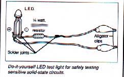
LED "Test Light" Construction, The current that is flowing through the LED test light circuit is calculated as follows: Charging system voltage minus voltage drop across LED, divided by the resistance (14 Volts - 1.2 Volts)/680 = 18.8 milli-amps (0.0188 amps). The lower the value of resistance, the more current that flows and the brighter the LED, up until the point the smoke gets out. Some LED's are sold in packages which detail the recommended maximum current allowed. Radio Shack should have the necessary components to build this LED test light. There are some newer "Super bright" LED's that some electronic supply houses carry that should work great in this application. I normally use two different colored. Wires (black/red) as the LED is polarity sensitive, the flat section on the LED lamp is normally the negative connection. Bolt lug terminals (U shaped) with one leg trimmed off, can be crimped on the wire ends to allow easy insertion into the fault code connector terminals. It won't hurt it if you connect the LED backwards, it just won't make any light.....the resistor can be connected in series on either the + or - wire to the LED. The US 1115 tool operates the same as the standard LED test light described above. The newer VAG1527B "may" be the type of LED test light, that uses 2 different colored LED's, so the test light will work when connected either way to ground and to +12V (i.e. with reverse polarity connections). This type of LED test light can indicate which connection is grounded and which connection has +12V without having to swap the test leads. As far as its use when checking instrument panel fault codes, the standard LED test lamp described above, should work fine. Engine Control Unit (ECU) Fault Code Listing 1990-94 Audi V8 [7] NOTE: The fault codes shown below indicate that the ECU has recorded a problem with one or more of the following: A system component, the wiring, the wiring connections, or from a engine mechanical problem (vacuum leak, low compression, etc.). If you get multiple fault codes recorded, step through the fault code reading sequence and write down all the fault codes that were recorded. After you locate the source of the problem for the "first" fault code you read, you may want to then clear all the fault codes stored and drive the car again to see if the other fault codes are stored again. In some cases multiple fault codes are recorded even though there may be only one problem with the system. Code Number Source of Fault code Possible cause Recommended Check or Repair Symptom in some cases
TRANSMISSION FAULT CODE LISTING
References: [7] Audi of America, Audi V8 Repair Manual Copyright © SJM Autotechnik™ , all rights reserved
Return to Troubleshooting Tips page. Return to SJM Autotechnik™ main page.
|
| About Us Privacy Policy Terms of Use Links Customer Service Safety Information Home |