|
Wiring Color Codes, ECU Pin Out, and Photos
Wiring Color Code Chart
W = White BK = Black OR = Orange BR = Brown CL = Clear R = Red Y = Yellow G = Green BL = Blue V = Violet (purple) GY = Gray LT.G = Light Green Note: Two color description means the wire has a main color and a "tracer" stripe along the wire of another color. i.e. R/Y = Red wire with Yellow Stripe Main ECU connector pin out, 25 pins. With the ECU removed from the car, and looking at release tang next to the pressure sensor port connection, Pin 1 is first pin on the bottom far left, Pins 2-13 follow on to the right, Pin 14 is first pin on the left, upper row, Pins 15-25 follow on the top row to the right.
1. Ground 2. Ignition Module Ground return 3. No connection 4. Hall Sender ground return 5. O2 Sensor shield 6. O2 signal wire 7. No connection 8. CIS Freq................ Valve 9. Ground 10. Coolant Sensor 11. RPM Sensor signal 12. TDC Sensor signal 13. TDC Sensor signal 14. Terminal 15 Ignition +12V 15. Idle Switch 16. Fuel Pump Relay control 17. Ignition Control Unit signal 18. Intake air temp sensor 19. Intake air temp sensor 20. Hall Sender + 12V 21. Full Throttle switch 22. Hall Sender timing signal 23. RPM sensor shield ground 24. RPM Sensor signal 25. TDC Sensor Shield ground
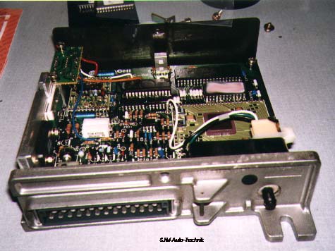
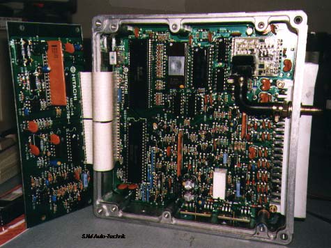
Here is what the inside of the MAC-02 looks like.
Main ECU connector pin out, 35 pins. When the ECU is installed in the car vertically, Pin 1 is the first pin on the right, closest to passenger door, i.e. towards the rear of the vehicle. (next to the connector release tab end). Pins 2-18 follow forward on the right side row. Pin 19 is the first pin on the left, with its position shifted slightly forward of Pin 1. Pins 20-35 follow forward on the left row. With the ECU removed from the car and looking at the ECU at the connector end, with the metal mounting tab down and to your right. The ECU connector Pin 1 is first pin on the bottom row to the left, Pins 1-18 follow on the bottom row to the right, Pin 19 is first pin on the top row to the left, Pins 19-35 follow on the top row to the right. 1. Cold Start Valve 2. Ignition Module Ground 3. no connection 4. Hall Sender return ground 5. ground 6. ground 7. Tachometer 8. CIS Freq Valve 9. Ground 10. Coolant Sensor 11. RPM Sensor signal 12. TDC signal + 13. TDC signal - 14. no connection 15. Knock Sensor Positive 16. Knock Sensor ground/shield 17. Boost Gauge 18. Ground 19. Waste Gate solenoid control 20. Idle Switch 21. Fuel Pump relay ground control 22. Ignition Module control signal 23. Intake Air Temp sensor ground return 24. Intake Air Temp Sensor + 25. Hall Effect +12V supply 26. Full Throttle Switch 27. Hall Sensor signal 28. RPM/TDC shield wire 29. RPM return ground 30. O2 Sensor shield ground 31. Fault code light control 32. Brake Light Switch 33. O2 sensor output 34. no connection 35. +12 Voltage from ignition switch
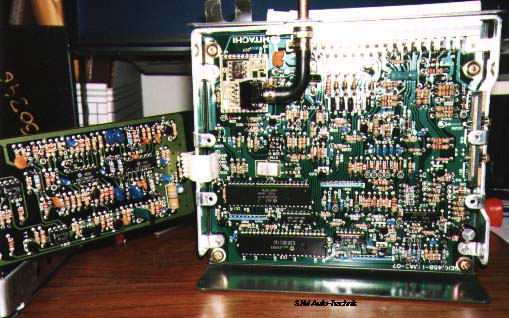
Here is what the inside of the MAC-07 ECU looks like.
Main ECU connector pin out, 35 pins. When the ECU is installed in the car vertically, Pin 1 is the first pin on the right, closest to passenger door, i.e. towards the rear of the vehicle. (next to the connector release tab end). Pins 2-18 follow forward on the right side row. Pin 19 is the first pin on the left, with its position shifted slightly forward of Pin 1. Pins 20-35 follow forward on the left row. With the ECU removed from the car and looking at the ECU at the connector end, with the metal mounting tab down and to your right. The ECU connector Pin 1 is first pin on the bottom row to the left, Pins 1-18 follow on the bottom row to the right, Pin 19 is first pin on the top row to the left, Pins 19-35 follow on the top row to the right. 1. Cold Start Valve 2. Ignition Module Ground 3. Charcoal Canister Filter solenoid (negative supply) 4. Decel Valve 5. N/C 6. Code wire, connected for Automatic Transmission cars 7. Tachometer 8. CIS Freq Valve 9. Ground 10. Coolant Sensor 11. RPM Sensor + (Y) 12. TDC signal - 13. TDC signal + 14. Over temp switch 15. Knock Sensor signal 16. Knock Sensor ground/shield 17. Boost Gauge 18. Ground 19. Waste Gate solenoid control 20. Idle Switch 21. Fuel Pump relay ground control 22. Ignition Module control signal 23. Intake sensor and Hall sensor ground return 24. Intake Air Temp Sensor 25. Hall Effect +12V supply 26. Full Throttle Switch 27. Hall Sensor signal 28. RPM/TDC shield wire 29. RPM return ground 30. O2 Sensor shield ground 31. Fault code light control (fuel pump fuse contact) 32. Brake Light Switch 33. O2 sensor output 34. California Code wire, connect for California vehicles 35. +12 Voltage from ignition switch
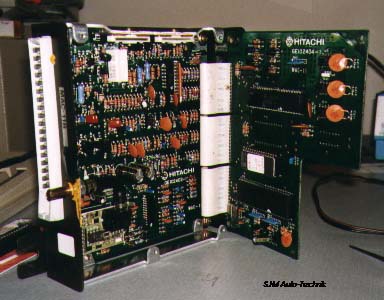
Here is what the inside of the MAC-10, MAC-11 and MAC-12 ECU's look like.
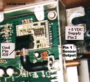
ECU Supply Voltage check and Pressure Sensor test If you have an intermittent running problem with excessive pinging and this is related to the dash boost gauge giving strange readings, the ECU internal pressure sensor may be having a problem. The ECU may store a 2222 fault code and the "Check Engine" light may also come on if the ECU pressure sensor is acting up. You should verify the hose from the intake manifold to the ECU is not leaking and make sure it has not come loose. If the ECU internal Pressure Sensor is not getting the correct boost pressure, the engine may ping very badly as the ECU will not know that it needs to retard the timing while under boost. With the ignition key on, but with the engine not running, you should see 0.9 to 1.0 bar on the dash gauge if you are near sea level altitude. The gauge reads out "absolute" pressure from 0.0 to 2.0 bar, above 1.0 you are seeing positive manifold pressure, i.e. turbo boost. You may also have a ground or +12V supply problem either on the engine or a problem with the supply power or ground to the ECU. You could also have a failure of the pressure sensor inside the ECU. If the dash problem is a separate problem and not related to the running of the car, it could just be a malfunction of the circuit board computer on the dash gauge pod assembly. You should check the ground wires that connect to the rear area on the intake manifold on the engine. Remove the bolt and make sure the threads are clean and re-tighten. The main ground strap on the engine down below near the left side engine mount should be checked as well. You should measure the +12V supply going to the ECU using a Digital Voltmeter. Pin 35 is the +12V supply, Check the voltage from pin 35 to both pins 18 and 9 as these two are the ground connections on the ECU. With the ignition key on, you should measure ~12-13 Volts across these pins. You may want to remove the one screw holding the ECU against the body and pull it out to make checking the voltages easier. Leave the ECU connector plugged in during the test. To check out the boost gauge signal coming from the ECU which comes from the internal Pressure sensor, connect a DMM across Pins 17 (+) and Pin 18 (-) and with the ignition key on, you should measure between 2.5 to 2.7 volts if you are near sea level altitude. This would correspond to a 0.9 to 1.0 reading on the dash boost gauge. These pins are the last two pins which are the farthest forward and next to the body when the ECU is mounted in the car. In other words, these two pins for the boost gauge output are ones hardest to get to. If you don't get this voltage reading then you might have a defective pressure sensor inside the ECU or a short between the ECU and the boost gauge assembly. If the wire from the boost gauge to the ECU is shorted, it should not really affect the operation of the ECU to control the engine, because inside the ECU this boost gauge output circuit is isolated from the rest of the internal pressure sensor signal used to control boost and timing. If you are really brave, you can remove the ECU cover and use a Digital Multimeter to test the pressure sensor. You want to see if it is getting a good + 5 Volt supply and see if it has the correct output voltage. There is a +5 Volt regulator inside the ECU that supplies power to this sensor and the other circuitry. Be VERY careful when probing around inside the ECU with the DMM. Pin 2 of the sensor is the +5V supply. The ground supply pin (19) on the pressure sensor is the one directly opposite Pin 2 on the other side of the pressure sensor. The sensor output voltage is on Pin 1. This sensor only uses three pins for operation, all the other pins are used to support the sensor and hold it off the circuit board. This sensor is used in the MAC-05, 07, 10, 11, 12, 13, and MAC-14 ECU's so this test can be used on these other ECU's. As mentioned before, with the ignition key on but with the engine off, the pressure sensor output voltage should be between 2.5 to 2.7 volts when the car is near sea level altitude. With a hand pump connected to the ECU sensor port, the sensor output voltage will rise up "close" to the 5.0 volt supply, (~4.95V) as the pressure applied is raised to 2.0 bar absolute. The stock dash mounted boost gauge will normally read up to ~2.0 bar, a few will read up to 2.1 bar but at that point it tops out and won't read any higher. the accuracy at this end of the range won't be very good. Here is a photo of the pressure sensor with the Ground, + 5 Volt and sensor output voltage connections marked.
Main ECU connector pin out, 35 pins. With the ECU removed from the car and looking at the ECU at the connector end, with the metal mounting tab down and to your right. The ECU connector Pin 1 is first pin on the bottom row to the left, Pins 1-18 follow on the bottom row to the right, Pin 19 is first pin on the top row to the left, Pins 19-35 follow on the top row to the right. 1. Cold Start Valve 2. Chassis 3. No connection 4. No connection 5. Chassis 6. No connection 7. Idle Stabilizer , Oil Pressure Warning Controller 8. CIS Frequency valve 9. Chassis ground 10. Coolant Temperature 11. Engine RPM Sensor 12. Ignition Timing Sensor 13. Ignition Timing Sensor 14. Electronic Thermo switch 15. Knock Sensor 16. Knock Sensor (shield for above) 17. No connection 18. Chassis ground 19. Waste gate Control Valve 20. Idle Switch 21. Fuel Pump Relay 22. Electronic Ignition, Power Stage 23. Air Temperature Sensor and Hall Sensor ground return 24. Air Temp Sensor 25. WOT, Full Load Switch 27. Hall Sensor 28. Shielding for 11, 12, 13, 29 29. Engine RPM Sensor 30. No connection 31. Fuel pump relay fuse holder, Fault codes 32. No connection 33. No connection 34. Chassis ground 35. +12V Power from ignition Main ECU connector pin out, 35 pins. When the ECU is installed in the car vertically, Pin 1 is the first pin on the right, closest to passenger door, i.e. towards the rear of the vehicle. (next to the connector release tab end). Pins 2-18 follow forward on the right side row. Pin 19 is the first pin on the left, with its position shifted slightly forward of Pin 1. Pins 20-35 follow forward on the left row. With the ECU removed from the car and looking at the ECU at the connector end, with the metal mounting tab down and to your right. The ECU connector Pin 1 is first pin on the bottom row to the left, Pins 1-18 follow on the bottom row to the right, Pin 19 is first pin on the top row to the left, Pins 19-35 follow on the top row to the right.
1. Cold Start Valve 2. Knock Sensor #2 Signal 3. Charcoal Canister Filter solenoid control signal 4. Decel Valve 5. Engine Control Lamp control (Tan connector) 6. T6F/4 Flash Code Connector W/BL 7. Tachometer 8. CIS Freq. Valve 9. Ground 10. Coolant Sensor 11. RPM Sensor signal 12. TDC Shield and ground 13. TDC Signal 14. Over temp switch 15. Knock Sensor #1 Signal 16. Knock Sensor ground/shield 17. Boost Gauge 18. Ground (O2 sensor) 19. Waste Gate solenoid control 20. Idle Switch 21. Fuel Pump relay control 22. Ignition Module control 23. Charcoal Canister shut off (small rear valve) 24. Intake Air Temp Sensor 25. Hall Effect +12V Supply 26. Full Throttle Switch 27. Hall Sensor timing signal 28. Tan diagnostic connector, upper terminal BL/Y wire 29. RPM Sensor Shield and ground. 30. O2 sensor signal 31. Blue Diagnostic Connector, upper pin Y/BK wire 32. Brake Light Switch 33. Black Diagnostic Connector, upper pin +12V BLK wire 34. Coding connector 35. +12V Ignition supply from Terminal 15 Here is what the inside of the MAC-14 ECU looks like.
Copyright © SJM Autotechnik™ , all rights reserved Return to Trouble-Shooting Tips page. Return to SJM Autotechnik™ main page.
|
| About Us Privacy Policy Terms of Use Links Customer Service Safety Information Home |