ECU Fault Code Retrieval,
ECU Output Tests
1987-88 5000S and 1989-91 Audi 100 with NF engine and CIS-E-III
Introduction:
Engine Control Unit (ECU) Fault Code System The 1987-88 5000S and 1989-91
Audi 2.3 liter 5 cylinder naturally aspirated engine (NF engine code)
with CIS-E-III fuel injection have a separate Fuel Injection Control
Unit and a separate Ignition control unit which are equipped with a
"self-diagnostic system"[2]. This system can test 14 input and 4 output
system checks.
Anytime an engine problem is occurring, this Fault Code system should
be used to first locate any system fault codes that have been recorded.
If the vehicle starts:You should drive the car for a minimum of 5-10
minutes and raise the engine speed above 3000 RPM and ensure that the
throttle is opened fully during the test drive. You want the engine
coolant temp to get above 80C, (176F).
If the vehicle does not start: Crank the engine with the starter for
at least 5 seconds. NOTE: The ignition should NOT be turned off after
doing this full throttle test road test or after the "No Start" cranking
test is done, as the fault memory may be erased. After doing the road
test or the "No Start" cranking test, proceed to the section below for
reading any fault codes stored during this process. The Check Engine
Warning light, should come on with the ignition key on if the bulb is
installed and functioning.
In some cases, people accidently remove a fuse they think is
a "SPARE" fuse in the fuse box but they end up disabling fuel or igntion
control systems on their engine.
The following fuses should be checked first.
(Fuse 13 for Fuel Pump),
(Fuse 21 supplies +12V to the black fault code connector and to the
Fuel Injection Control Unit (FICU) memory),
(Fuse #26 is for Check engine light bulb),
(Fuse #27 is for the Ignition Control Unit).
FUSE #28 is often mistaken as a SPARE fuse, it is not!
Fuse #28 is for the FICU and for the FICU controlled solenoids.
These all should be checked if the fault code system or the engine fuel
system does not operate as expected. 1987-88 5000S, check the wiring
diagram for details on which fuses are used for this system. The Black
fault code connector should have +12V on the top pin, and ground on
the bottom pin. Check engine and vehicle grounds if Fuel Injection or
Ignition Control units are suspected as being faulty.
Switch A/C system off during fault code retrieval. For the 1989-91 Audi
100, apparently there are two versions of the CIS-E-III fault code memory
system, one for 49 state vehicles, and one for California Vehicles with
slightly different emission control systems. The 49 State version has
Temporary Fault code storage which will be erased each time the ignition
is turned off. The 49 State version uses the 443-906-264C Fuel Injection
Control Unit and the 443-907-397C Ignition Control Unit.
The California version has permanent fault code memory which retains
the fault codes even after the ignition has been turned off [2].
(Note: Part numbers are for reference only, consult your local Dealer
parts department for the latest part number information.)
Fault Code Reading, 1987-88 5000S, 1989-91
100
The later 89 -91 Audi 100 uses two diagnostic connectors one black and
one brown, under the driver side dash.
The 1987-88 5000S and the early 1989 Audi 100 do not have these diagnostic
connectors installed. The fuse in the top of the fuel pump relay can
be inserted for 4 seconds to initiate the fault code sequence in the
early system without the diagnostic connectors under the dash.
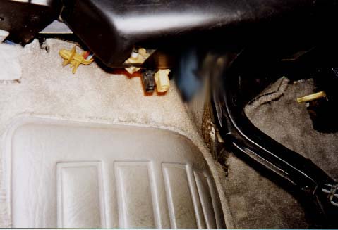
If you don't have the diagnostic connectors and you don't have the "Check
Engine" light bulb installed in the instrument cluster, you will need
to connect the test light to one of the Fuel Pump Relay contacts (Contact
"L") and connect the other end of the test lamp to +12V in order for
the ECU to blink this light so you can read out the fault codes.
Here is a picture showing the connections between the fuel pump relay
and the two Engine control units and the connection of a test lamp to
one of the terminals in the top of the fuel pump relay, in order to
blink out the fault codes.
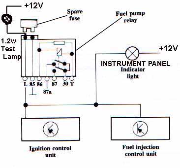
Diagram Courtesy of Audi of America
If you do not have the light bulb installed in the dash, but you DO
have the diagnostic connectors, you will need to connect an LED or low
wattage light bulb (12 volt, 1.2 Watt) across these color coded diagnostic
connectors in order to have the fault codes blinked out.
To initiate the fault code system in the late 1989 Audi 100 and 1990-91
Audi 100, a jumper wire and LED can also be inserted into the fault
code connectors under the dash instead of using the fuel pump relay
fuse insertion method.
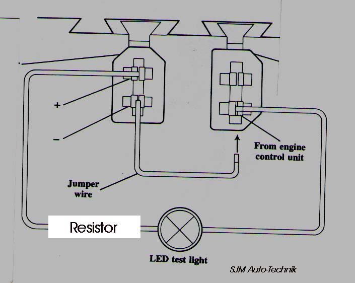
Diagram courtesy of Audi of America
IMPORTANT DETAILS: This yellow "Check" engine light will normally come
on when the ignition is turned on "if" the bulb is installed in the
dash. The operators manual refers to this "Check" engine light as the
"Emission Control System (ECS)
malfunction Indicator Light."

Diagram courtesy of Audi of America
Some of the Audi 100's have no "check engine" light bulb installed in
the dashboard assembly even though the circuitry is there. Normally
this bulb is installed in-between the "Airbag" light and the "Door Open"
warning light on the right side of the dash and this light should come
on when the ignition key is first turned on.
If you do not have the light bulb installed in the dash, you will need
to connect an LED or low wattage light bulb (12 volt, 1.2 Watt) across
these diagnostic connectors in order for the ECU to blink this light
so you can read out the fault codes. Vehicles produced for sale in California
should have this "Check Engine" light bulb installed in the dash. The
documentation for the late 1989 Audi 100 and the 1990-91 Audi 100 shows
a black and brown connector, but no blue connector.
Connect the LED positive terminal (LED's are polarity sensitive) to
the top black terminal, and the negative LED terminal to the bottom
terminal in the brown connector as shown. Use a jumper wire between
the bottom black connector terminal and the same bottom terminal in
the brown connector to short for 4 seconds then remove jumper, to initiate
the fault codes (ignition key on, with or without the engine running).
Check the Bentley Manual for additional information.
BLINKING OUT THE FAULT CODES
As mentioned, with the ignition on or with the engine idling, you activate
the fault code system by inserting the fuse in the top of the fuel pump
relay for four seconds OR by connecting the jumper wire across the two
diagnostic terminals under the dash for four seconds, after removing the
fuse or jumper, the diagnostic system will then begin the sequence to
blink out the fault codes via the instrument panel "Check" Engine light
or by flashing the LED connected across the diagnostic connectors. Each
fault code consists of four groups of pulses. The sequence for displaying
the fault codes is a start sequence of 2.5 seconds with the lamp on, and
2.5 seconds pause with it off.
Then the fault code output follows as a half-second pulse with the LED
light on, separated by a half-second pause with the LED light off, with
a larger pause of 2.5 seconds between each set of pulses. Example:If no
fault codes are stored, code 4444 will be displayed by the Control unit
flashing the LED.
The control units will flash the LED on and off as follows after the jumper
wire is inserted into the connectors for 4 seconds and then removed. LED
on (2.5 sec), LED off (2.5 sec) Now here comes the code 4444 Blink, pause,
Blink, pause, Blink, pause, Blink, (2.5 second pause) Blink, pause, Blink,
pause, Blink, pause, Blink, (2.5 second pause) Blink, pause, Blink, pause,
Blink, pause, Blink, (2.5 second pause) Blink, pause, Blink, pause, Blink,
pause, Blink, (2.5 second pause)
For example: Code 2322 (Air Temperature sensor) would be displayed as
follows:
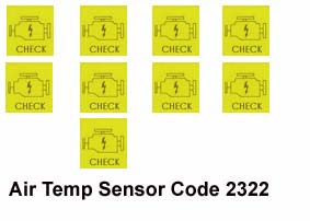
The sequence of displayed pulses will repeat until the system is stepped
to the next fault code stored (if any) by connecting the jumper wire across
the connectors again for 4 seconds. The LED will blink once at 2.5 second
intervals to indicate that the last error code has been read. Use a note
pad to write down the fault codes as they are displayed and then check
for the specific fault code description listed in the section below. Check
the Bentley Manual for additional information.
In my 1989 200TQ, I have permanently connected a momentary push button
switch across the two jumper wire connections so that I only need to push
this button to activate the fault codes. I ended up installing the "check"
engine light bulb back in the dash to avoid having to use the LED connected
under the dash.
Permanent Fault Code Memory Erasing, 1989-91
Audi 100 with CIS-E-III (California Vehicles Only) On California vehicles,
the permanent fault code memory can be erased by stepping through the
Output test below, then after the 4 output tests have been completed,
the check engine light/LED should blink on for 2.5 seconds, then off for
2.5 seconds. Now, Insert the fuse or jumper again for 10 Seconds, then
remove the fuse/jumper and the fault code light should stay on continuously,
indicating the fault code memory has been erased. This may also be possible
on the 1987-88 5000S, but I have not verified this.
Output Tests 1987-88 5000S, and 1989-91
Audi 100 with CIS-E-III There is also an "output test" mode that will
enable the Control unit to energize the CIS differential pressure regulator
and cycle the electrical solenoids on and off to verify they are working
correctly.
The full throttle switch must be working correctly to initiate these output
tests. To activate the Output Tests, you must first insert the fuse into
the fuel pump relay, or connect the LED and the jumper wire to short across
the Fault Code Connectors as shown and THEN turn on the ignition to start
the output tests. Remove the fuse or jumper wire after 4 seconds:
- (Test #1) The code 4341,will be displayed by the fault code light/LED.
The Differential Pressure Regulator with have 10 milli amps applied
to this regulator when the full throttle switch is manually closed.
100 milli amps when the throttle switch is open
- Insert the fuse, or connect the jumper wire again for 4 seconds
to go to the next output test:
- (Test #5) Code 4343, Close the full throttle switch again, and the
Carbon Canister Solenoid valve is cycled on and off.
- Insert the fuse, or connect the jumper wire again for 4 seconds
to go to the next output test:
- (Test #2) Code 4431, will be displayed. Close the full throttle
switch and the Idle Stabilizer valve cycles.
- Insert the fuse, or connect the jumper wire again for 4 seconds
to go to the next output test:
- (Test #4) Code 4443, Close the full throttle switch and the Cold
Start Valve will be cycled on and off for 10 seconds,
- (Test #7) Code 0000, End of Output Test Procedure (Light on for
2.5 seconds, then off for 2.5 seconds indicates code 0000)
- Again, check the Bentley Manual for more details.
LED "Test Light" Construction, for blinking
out fault codes. (1989-91 100) The LED with a series resistor is normally
connected across two terminals on the fault code connectors. The LED normally
needs a resistor in series to limit the current, most LED's operate with
10-30 milli-amps (0.010 to 0.030 amps).
A 1/4 watt 680 ohm resistor works pretty well but you don't have to use
a resistor with exactly 680 ohms. The current that is flowing through
the LED test light circuit is calculated as follows: Charging system voltage
minus voltage drop across LED, divided by the resistance (14 Volts - 1.2
Volts)/680 = 18.8 milli-amps (0.0188 amps).
The lower the value of resistance, the more current that flows and the
brighter the LED, up until the point the smoke gets out. Radio Shack should
have the necessary components to build this LED test light. There are
some newer "Super bright" LED's that some electronic supply houses carry
that should work great in this application. Here is a diagram that illustrates
the connection of the resistor in series with the LED.
Diagram courtesy of Audi of America
I normally use two different colored. wires (black/red) as the LED is
polarity sensitive, the flat section on the LED lamp is normally the negative
connection. Bolt lug terminals (U shaped) with one leg trimmed off, can
be crimped on the wire ends to allow easy insertion into the fault code
connector terminals.
It won't hurt it if you connect the LED backwards, it just won't make
any light.....the resistor can be connected in series on either the +
or - wire to the LED.
Fault Code Listing [2] [3]
NOTE: The fault codes shown below indicate that the Control unit has recorded
a problem with one or more of the following: A system component, the wiring,
the wiring connections, or from a engine mechanical problem (vacuum leak,
low compression, etc.). If you get multiple fault codes recorded, step
through the fault code reading sequence and write down all the fault codes
that were recorded.
After you locate the source of the problem for the "first" fault code
you read, you may want to then clear all the fault codes stored and drive
the car again to see if the other fault codes are stored again. In some
cases multiple fault codes are recorded even though there may be only
one problem with the system. Code Number Source of Fault code Possible
cause Recommended Check or Repair Symptom in some cases
- 1111 Fuel Injection Control Unit (FICU) or Ignition control unit
(ICU) Defective Check vehicle electrical system grounds, Replace control
unit if no wiring or +12V supply faults found
- 1231 (1989-91 Audi 100 only) Transmission speed sender (G68), Signal
used by Ignition Control Unit (ICU), check sensor output. Disconnected
wire between instrument cluster and Fuel Injection Control Unit. Check
instrument cluster internal circuit board connection pin solder joints.
Instrument cluster repair
- 2121 Idle switch Switch open ckt, stuck closed Switch defective,
mechanical linkage problem, or wiring problem
Also check speedometer speed sensor in transmission, and wiring from
sensor to speedometer in instrument cluster. Faulty speedometer signal
can cause stalling. Poor solder connections in the instrument cluster
is usually the cause.
- 2122 Engine speed sensor signal missing. Signal used by Ignition
Control Unit, Hall sender (G40) faulty, Disconnection between terminal
17 of Ignition Control unit (J154) and terminal 30 of Fuel Injection
Unit (J21). No RPM signal from Ignition Control Unit (J154) to Fuel
Injection control unit via knock control. Ignition Control Unit (J154)
or related wiring defective.
- 2123 Full load/full Throttle switch Switch open ckt, stuck closed
Switch defective, mechanical linkage problem or wiring problem
- 2132 1989-91 Audi 100 Only Data Wiring Defective, check wiring (California
Vehicles only)
- 2141 Knock regulator Regulator limit exceeded, Excessive knock,
timing is being retarded by maximum amount, Fuel octane too low, Excessive
Compression, carbon build up in combustion chamber
- 2142 Knock sensor Open or short circuit, Defective sensor Check
sensor and wiring Symptom: Timing retarded, High fuel consumption,
power loss,
- 2223 Altitude Sensor defective, check sensor output and wiring
- 2232 Air Flow Meter plate rotary Potentiometer (resistive Sensor)
defective, check sensor output and system wiring
- 2233 Air Flow Sensor (G70) Reference voltage, Disconnection between
terminal 26 of Fuel Injection control unit (J21), and terminal 21
of Ignition control unit (J154)
NOTE: The reference voltage for load and altitude signals is monitored
by the CIS-E-III Fuel Injection control unit and NOT as indicated
on the VAG 1551/1552 diagnostic tester. The reference voltage is from
the Air flow sensor potentiometer. NF engines do not have an Air Mass
Sensor, they use a Potentiometer on the air flow meter assembly below
the fuel distributor..
- 2312 Coolant sensor Open or short circuit, Defective sensor or wiring
Symptom: Cold starting difficulties at low temperatures, Poor idle
and acceleration during warm up
- 2341 Oxygen Sensor Control Regulating Limit exceeded
- 2411 1989-91 Audi 100 only Exhaust Gas Recirculation Valve, (California
Vehicles only)
- 4431 Idle Stabilizer Valve (ISV), Signal used by Ignition Control
Unit
- 4444 No Faults have been recorded.
- 0000 End of Diagnostic Output, code 0000 is signaled by the Check
Engine or LED light coming on for 2.5 seconds, and then being off
for 2.5 seconds
References: [2] Audi 100, 200 Official Factory Repair Manual Volume
1, Robert Bentley Corporation
References: [3] Audi of America, Technical service training publications:
"1986 Model Change Information-publication
"1989 Model Change Informaton-publication All rights reserved.
"2.3 Liter Engine with CIS-E III Engine Control System"
(Dec./1986)
Copyright © SJM Autotechnik™ , all rights reserved
Return to Troubleshooting Tips page.
Return to SJM Autotechnik™ main
page.