|
Instrument Cluster Electrical Repairs 1986-88 Audi 5000 Turbo/Quattro, 1989-91 Audi 100, 200 Turbo/Quattro 1992-95 100/S4/S6 (some information applicable)
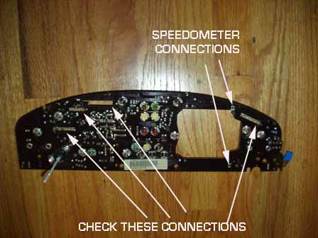
Usually these problems are caused by poor solder joints (cracked joints) on the Instrument cluster circuit boards where the wiring connector pins are soldered to the board. The AUTO CHECK, TRIP COMPUTER Display connector solder pins may also need to be repaired, See details below. Normally you have to remove the IC from the dashboard and disassemble the IC to remove the upper Auto-Check circuit board, as well as the main instrument/speedo/tachometer circuit board and then resolder all the connector pins on the circuit board(s) as well as the 2 pin connectors that cause problems with the speedometer operation. Also resolder the connections on the black diodes if you have both of the turn signal lights coming on when the headlamps are turned on.
Details on disassembling the IC for repairing the speedometer and other intermittent connection problems can be found in the next section below Exploded View of the cluster is on this page HERE When you re-install the Instrument cluster, you may also want to use some contact cleaner/enhancer on the connections where they plug into the instrument cluster.
If you can't find the Stabilant 22A, then visit your local Electronics Supply house and use their recommended contact cleaner and contact enhancer. Caig makes some nice products.
Audi issued a service bulletin #95-02 describing the use of Stabilant 22A fluid to help eliminate problems with poor or intermittent electrical connections. Stabilant 22A enhances conductivity and should be applied to the connector terminals whenever a harness is disconnected as well as when replacing a component or connector.
When applied to electrical connections, Stabilant 22A becomes a conductor and provides the reliability of a soldered connection, without actually bonding the contacting surfaces together.
When applied to multiple pin connectors, Stabilant 22A enhances conductivity between connector terminals while remaining a non-conductor between adjacent terminals.
This fluid can be used to eliminate some of the problems that occur with the connectors on the back of the instrument cluster.
The Bulletin lists the part number as ZVW 186 001 which may be available from the VW dealer at a reasonable cost.
There is also a web site for the Stabilant product at Stabilant Web site, which may have locations for purchasing this contact enhancer. Normally this fluid is extremely expensive and sold in small containers, so use sparingly. Audi cautions that this fluid should not be used on the oxygen sensor connector terminals.
Dash Speedometer Inoperative or Intermittent: Scrambled Auto Check "OK" display Repair, Faulty Trip Computer operation repair 1990-91 Audi 100 Engine Stalling
If the speedometer needle bounces around or is intermittent in operation, there may be a problem with some solder joints on the back of the instrument cluster circuit board. In some cases on the 1990-91 Audi 100, this can cause intermittent
stalling on deceleration. If the speedometer does not work at all, check fuse #12, as this fuse supplies +12V to the speedometer sending unit in the transmission and in some vehicles supplies +12V to the speedometer itself. This fuse #12 also supplies +12V to the back up lights. Speedometer Sensor in Transmission:
1989-94 Audi 100/200, 1988-95 Audi 80/90, 1996-2004 Audi A4/A6 The sensor is held by a spring clip, then the sensor is rotated clockwise 1/4 turn and pulled up and out. You can test the sensor out of the transmission with the same DMM ohm meter function resistance test across the 2 terminals, then place a magnet near the tip, the resistance should go open circuit (infinite ohms) when the magnet is close to the tip of the sensor. Remove the instrument cluster: The airbag power supply wire should be disconnected before removing the steering wheel. See the Suspension section for details on disabling the air bag power supply.
Remove the lower trim piece Phillips screws (3) below the instrument cluster. Then remove the screws securing the instrument cluster to the dash. You may want to place some protective tape over the dash and dash wood to prevent scratching them during the instrument cluster removal.
Pull out the instrument cluster while reaching around to disconnect the electrical connectors. Some of the connectors have a colored center plastic locking tab, that must be popped up, BEFORE you attempt to pull the electrical connector off the back of the cluster. Use a curved dental pick to pop up this center tab on the connectors. One of the smaller connectors will need to be squeezed together to release the tangs. There usually are 2 to 3 small bulbs with twist lock bases, that need to be rotated counter clockwise to remove them from the right side of the instrument cluster.
You may have to snip off a plastic wire zip tie around one of the electrical cables.
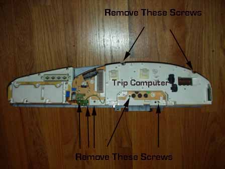
After the Instrument Cluster (IC) has been removed from the dash, you will need to disassemble the cluster to gain access to the circuit board(s) with the intermittent connections.
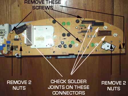
First remove the 5 screws holding the white cover which has the trip computer circuit board. The 2 screws holding the small circuit board on the lower left also need to be removed.
Now the main circuit board on the back of the cluster will have to be removed, after removing the 4 screws, and the 4 nuts holding the gauges to the board. You may want to mark the location of the screws holding the main circuit board, as they can get mixed up with the screws holding the white plastic cover.
Some Instrument clusters use Phillips screws, the later ones may use torx screws. In some cases the other gauges will come up with the circuit board or they may stay in the front part of the IC. Carefully pry/pull up the main board and handle this carefully and watch for any spring for the trip computer reset. The main circuit board has several pin connections that need to be popped loose in order to pull up the board.
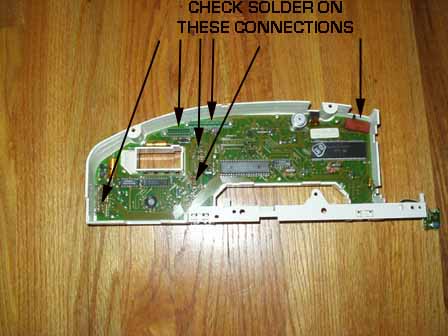
SPEEDOMETER AND OTHER CONNECTIONS REPAIR INFO: 1989-1991 Audi
100/200 As far as the intermittent speedometer connections are concerned,
use a magnifying glass to inspect the back of the circuit board at the
following areas. If your cluster has the problem with the Left and Right turn signal
lights and the high beam indicator light coming on dimly when the headlights
are turned on, your instrument cluster circuit board may have a poor
connection on one solder joint of the black colored 26 pin connector.
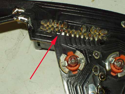
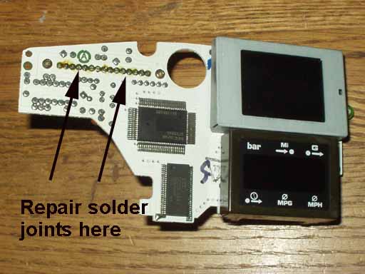
Use a low wattage iron, less than 30 watts and some solder wick to remove the old solder, then re-solder with some mild rosin core electronic solder. Don't use any acid core solder! AUTO CHECK, TRIP COMPUTER DISPLAY Connector solder joint repair The Auto check and Trip computer display connector pins can also have cracked solder joints, you may need to resolder these pins as shown below.
Illumination Bulbs: 1.2 watt white base bulbs, black base 1.2 Watt bulbs, 1.5 watt brown
base bulbs and 2.0 watt green base bulbs were originally used.
Some of the warning lamp bulbs have red or yellow colored rubber sheaths that can be removed and transferred to the new bulbs. See below for the number of bulbs used for each model of Instrument cluster
Note: Plastic polish or clear coat scratch remover can be used to polish small scratches in the instrument cluster plastic face plate.
Instrument Panel (IP) Light Bulb Replacement, other small interior bulbs: 1986-88 5000S/T/TQ
The following list should assist in Instrument Panel (IP) Bulb replacement. The instrument panel bulbs come with a plastic base that holds the bulb and has exposed contacts. The bulb/holder is inserted into the hole in the back of the instrument panel and then twisted 90 degrees clockwise to retain the bulb holder and make contact with the instrument panel connections. Using a pair of needle nose pliers helps grip the bulb holder and install or remove the bulb/holder.
Keep in mind that these bulbs can be very expensive if purchased from the dealer, in some cases they cost over $4 each, and when you need 10-15 of these for each instrument panel to replace all the illumination bulbs and the other indicator bulbs, things add up quickly.
I recommend you replace all the bulbs while you have the instrument panel out of the car to avoid having to do the job over as the other indicator or illumination bulbs burn out a short time later.
If you can't replace all the bulbs, at least you should use an DMM, i.e. an ohm-meter to test each bulb for continuity and replace all the defective ones.
Instrument Panel (IP) Light Bulb Replacement, Other small interior bulbs:
The following list should assist in Instrument Panel (IP) Bulb replacement, the 1989-91 vehicles use instrument panel bulbs with the different shaped housing contacts than what was used in the 1986-88 5000S/T/Q. The instrument panel bulbs come with a plastic base that holds the bulb and has exposed contacts. The bulb/holder is inserted into the hole in the back of the instrument panel and then twisted 90 degrees clockwise to retain the bulb holder and make contact with the instrument panel connections. Using a pair of needle nose pliers or small screwdriver helps grip the bulb holder and install or remove the bulb/holder.
I also recommend you replace all the bulbs while you have the instrument panel out of the car to avoid having to do the job over as the other indicator or illumination bulbs burn out a short time later.
If you can't replace all the bulbs, at least you should use an DMM, i.e. an ohm-meter to test each bulb for continuity and replace all the defective ones.
Oil Pressure Gauge/Warning system problems 1989-91 Audi 100/200
The Oil pressure gauge and the Oil Pressure warning system (Auto-Check System) uses two oil pressure sending units. There is a small white colored 1.8 bar single wire sensor which is used above 2000 RPM to warn of low oil pressure (less than 1.8 bar).
In some cases poor connections inside the instrument cluster (IC) can cause false oil pressure warnings/beeps, so if the oil pressure sensors check out ok, you may need to remove the IC and resolder all the connector terminals on the Auto Check and cluster circuit boards.
There is also a larger diameter 2 wire gauge sending unit which provides a varying resistance output for the instrument panel oil pressure gauge (Terminal G on the sending unit, black connector).
This gauge sending unit also has a 0.3 bar warning connection (WK) for the Auto-Check system oil pressure warning system which uses a colored coded connector terminal (BLUE).
These sending units are located on the driver side of the engine block, underneath the lower radiator hose area.
Normally with the ignition key on, the oil pressure gauge will read near 0 bar. If the gauge is pegged all the way up to over 5 bar with the ignition key on, or with the engine running, you may have defective gauge sending unit. Try grounding the G terminal wire with the ignition key on, the gauge should read near O bar.
With the 2 wires disconnected from the gauge sending unit, and the engine off, you should measure approximately 5-10 ohms resistance on the G terminal to engine ground. At idle the sending unit gauge output terminal G resistance should be around 70-120 ohms depending on oil temp/viscosity. With the engine running around 3000 RPM, you should measure 170-200 ohms on this G terminal to engine ground. With the engine off you should measure less than 1 ohm on the WK terminal to engine ground, with the engine running the resistance reading should go very high (i.e. Mega-ohms or Infinity)
The small white single wire 1.8 bar oil pressure warning sensor should connect the terminal to ground when the oil pressure is above 1.8 bar, i.e. when the engine is running over 2000 RPM.
The replacement oil pressure gauge sending unit should be marked with a 0-5 bar, and 0.3 bar output near the threaded portion.
There is another sending unit used on other Audis/VW's BUT it is not the correct sending unit as it incorporates the 1.8 bar warning operation.
On the 10V Turbo Engines, 1986-90 Audi 5000T/Q, 1989-90 Audi 200T/Q, the easiest way to remove the large oil pressure gauge sending unit, is to remove the 2 wire connectors from underneath, and then remove the two 5mm allen screws from the warm up regulator on the side of the engine block, and lay the warm up regulator on top of the valve cover out of the way. Gently pry the metal coolant pipe away from the block so you can get a thin 17mm open end wrench down between the engine block and the coolant bypass hose onto the sending unit to loosen it.
W = White BK = Black OR = Orange BR = Brown CL = Clear R = Red Y = Yellow G = Green BL = Blue V = Violet (purple) GY = Gray LT.G = Light Green
Note: Two color description means the wire has a main color and a "tracer" stripe along the wire of another color.
i.e. R/Y = Red wire with Yellow Stripe
Wiring Size, Metric Conversion to AWG
Copyright © SJM Autotechnik™ , all rights reserved
Return to Troubleshooting Tips page. Return to SJM Autotechnik™ main page.
|
||
| About Us Privacy Policy Terms of Use Links Customer Service Safety Information Home |