|
Suspension/Steering/Wheels,
Technical Tips, 1986-91 5000/200TQ
Flushing the Hydraulic System
Steering Wheel Play? Car jerks right or left when you hit a groove in the road? Rattling, Clunking or Popping Noise when you first turn the wheel?
Mineral Oil for Hydraulic Power Steering/Brake System
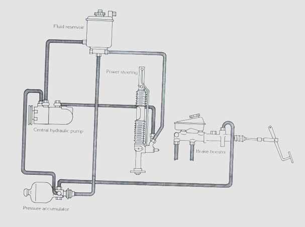
Audi recommends using only a mineral oil based fluid for the hydraulic power steering/brake system. This is for the large reservoir mounted on the firewall to the left of the brake master cylinder (RHD).
Pentosin is the manufacturer for the Audi factory fluid part number G 002 000. The Audi 5000 up to the 1989 models used the Pentosin CHF 7.1, in 1989 they went to a Pentosin CHF 11S which is a synthetic version with an improved temperature range.
The Pentosin cans indicate that the CHF 7.1 and the CHF 11S should not be mixed together, although the Audi service bulletins listed below say it is ok to mix them. Best advice if you are unsure which fluid was used in your car, is to flush out the old fluid when you had the new version (CHF 7.1 or 11S)
A quick look at the Pentosin CHF 7.1 container (white colored metal container with green cap), and at the Pentosin CHF 11S, (green colored metal container with red cap) provided the following information.
Pentosin CHF 7.1
Hydraulic system mineral oil for level control systems, hydro pneumatic suspension, shock absorber, power steering. Range of operation, -40C to +100C, especially recommended for countries of cold climate. Close container after use. Very Important: Pentosin CHF 7.1 should not be mixed with Pentosin CHF 11S or any other hydraulic oil BMW Teile Nr: 81 22 9 407 549 Green Color fluid
Pentosin CHF 11S
Synthetic Oil for central hydraulic systems, level control, hydro pneumatic suspension, shock absorber, power steering. Range of operation: -40C to +130C, especially recommended for countries of cold climate. Close container after use. Very Important: Pentosin CHF 11S should not be mixed with Pentosin CHF 7.1 or any other hydraulic oil. BMW Teile Nr: 81 22 9 407 758 USA BMW Teile Nr: 82 11 1 468 041 Porsche Teilenummer: 000.043.203.33 Olive Color fluid (Olive color, is defined as "yellow green")
2 of my local wholesale parts source list the Pentosin CHF 11S as the G 002 000, and the Pentosin CHF 7.1 is listed by them as the G 002 000 G. (The "G" means Green?) The CHF 7.1 costs 25% less than the CHF 11S from these suppliers. FLUSHING THE HYDRAULIC SYSTEM
I have used the synthetic Pentosin 11S in 1986-88 5000S/T/Q vehicles with no problems. On high mileage vehicles, I like to flush out the system to get the older fluid type out. I use Pentosin 11S as the flushing fluid, I remove the fluid reservoir and drain out the existing fluid, and strain it through a paint paper filter to look for excessive black rubber crud, and metal fragments in the reservoir.
Most Power Steering rack rebuilding companies usual won't warranty a rebuilt rack or pump failure unless all of the rubber hoses are replaced, as well as ensuring there are no metal fragments coming from the pump when only the rack is changed.
You should use some brake cleaner spray to completely clean out the reservoir. The filter/screen can be pulled up and out of the reservoir with some needle nose pliers. If this screen gets plugged up with rubber junk bits, the power steering system can be noisy. These filter/screens are available if you want to replace it.
When I flush out the fluid from the steering and brake system, I start out by re-installing the clean hydraulic reservoir with the return line fittings capped off, (so fluid won't leak out of the reservoir). Then I take all the return hoses coming from the brake accumulator, the brake power servo, and from the power steering rack that were connected to the fluid reservoir, and put them into a waste bucket (old coffee can) to collect the old fluid coming out of these systems.
Now I run the engine briefly as I quickly pour in clean Pentosin CHF 11S into the reservoir and watch the old fluid go into the waste bucket. You can briefly turn the steering wheel back and forth with the front wheels off the ground to get clean fluid going through the rack, you can also pump the brake pedal many times, with and without the engine running to flush out the power booster and accumulator and hopefully get clean fluid through these two areas. Make sure the reservoir is kept full during this procedure. Having a helper in the car to turn the steering wheel and who can turn off the engine quickly is a good idea while you pour clean fluid into the reservoir and watch the old fluid pour out of the return hoses into the coffee can. This can be a messy procedure......
My personal 89 200TQ had a rebuilt rack installed by a local shop before I purchased the car used, the shop used CHF 7.1 as indicated on the repair order. After purchasing the car, I flushed out the system using CHF 11S, and after 50,000 additional miles have not had any leakage from the rack. I did have to reseal the P/S pump at ~100k miles, but this is not unusual. The car came with a new brake accumulator (bomb) before I bought it. About 6 months ago, I changed the pressure hose from the pump to the bomb due to seepage.
The 1984-87 5000S/T/Q vehicles had many updates/changes that occurred to the hydraulic system in the form of improved steering racks, improved hoses, different new and rebuilt pumps, each with different suction/pressure hose fitting bolts with different orifices, so check the hose fitting bolts when replacing the pumps on these vehicles. The Bentley and the service bulletins should have this information. Of course all of the improvements didn't totally eliminate leakage/failure of these components......
The ZF catalog lists one rebuilt "short" rack for all the 1978-90 5000/100/200 vehicles which is interesting, it was my understanding that the early 1978-83 5000 vehicles used ATF in the power steering system. Possibly the rebuilt rack seals will work with either type of fluid.
AUDI Service Bulletin on the change from the Pentosin 7.1 to the new Pentosin 11S Synthetic hydraulic fluid.
From the set of microfiche Audi Service Training bulletins (Oct. 1994)
Nov: 89 Bulletin # 48-89-T07 Hydraulic System Fluid New Type Hydraulic Fluid has been improved as of MY 1990 NEW: Hydraulic Fluid: Part number is Unchanged (G 002 000) This Fluid is more temperature resistant Color: Olive
OLD: Hydraulic Fluid P/N G 002 000 Color: Green
The new hydraulic fluid can be identified by the "red" cap on the container. NOTE: New and Old fluid can be mixed if necessary
Power Steering Pump Replacement Audi 5000, Using the Correct Banjo Bolts
Audi issued a Product Circular Group 48, Number 87-02 July 22, 1987 outlining the installation of a rebuild Power steering pump.
For the Rear Pressure Port that connects to the steering rack: T he pumps with a red tag should use the banjo bolt with small hole Audi part number N 903 246 01. For pumps with a sliver tag use the banjo bolt with three large holes and no screen, Audi # N 021 071 2
For the suction line from the reservoir: Silver pumps, check the code number on the tag at the top next to the ZF Made in Germany Info. .
Red Tag Pumps with any code number: Use Part number Audi N 902 669 01 with 2 grooves on the banjo bolt head STEERING WHEEL REMOVAL WITH AIRBAG
PLEASE NOTE: THE AIRBAG SYSTEM IN YOUR 1989-91 AUDI IS DESIGNED TO SAVE THE LIFE OF THE DRIVER DURING A SEVERE FRONTAL COLLISION.
IT IS CRITICAL THAT ANYONE SERVICING OR REPAIRING THE AIR BAG SYSTEM ARE QUALIFIED TO PERFORM SAID REPAIRS AND CHECKS. IF IN DOUBT, HAVE YOUR LOCAL AUDI DEALER SERVICE YOUR AIR BAG SYSTEM.
THE MECHANIC, SERVICE TECHNICIAN OR VEHICLE OWNER COULD BE HELD RESPONSIBLE AND LIABLE FOR ANY DAMAGES OR DEATHS CAUSED IF THE AIR BAG SYSTEM MALFUNCTIONS DUE TO THEIR NEGLIGENCE.
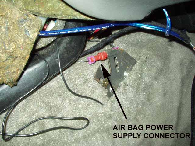
STEERING WHEEL REMOVAL: The steering wheel removal procedure for the 1989-91 200TQ cars with an airbag does indicate that you must disconnect the airbag power feed red connector. THE BENTLEY REPAIR MANUAL SHOULD BE CONSULTED BEFORE WORKING ON YOUR AIR BAG SYSTEM.
This red single wire connector is located in front of the center console area, behind the passenger side center console "side" trim cover. This is the trim cover that extends forward of the center console area, partially under the dash, just in front of the area where the ash tray is located.
NOTE: The 1992-95 Audi S4 has this air bag power connector located in a different location, above the ECU mounting area on the passenger side floor area behind the carpet, at the top of the plastic housing above where the circuit breakers are mounted. You will likely need to remove the plastic cover over the Engine Control Unit, to find this Airbag connector. Details on removing this plastic cover can be found HERE.
Disconnecting the vehicle battery WILL NOT DISABLE THE AIR BAG CIRCUIT!!!
You should avoid turning on the ignition when the air bag is removed, as the air bag control unit may store a fault code.
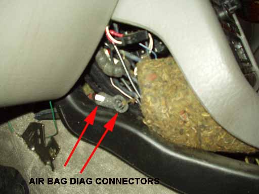
The later air bag control unit that is part of the air bag KF recall, appears to allow a temporary disconnection of the air bag, and will reset itself in some cases to clear the code after the air bag has been reconnected. In some cases you may have to use the VAG1551/2 factory or PC based scan tool to clear the codes if the control unit does not reset itself. If your 1989-91 Audi 100/200 or 1992-93 Audi 100/S4 has had the KF campaign air bag recall work completed, there will be two fault code connectors (one black and one white connector) located behind the center console side panel on the drivers side, that will allow connecting the VAG1551/2 Scan tool to clear any stored codes. The 1994 and later Audi 100/S4/A6/S6 normally use the standard diagnostic connectors under the hood in the relay box to communicate with the all the vehicle control units including the air bag control unit. For the earlier 1989-91 Audi 100/200 vehicles, this center console side panel is located about where the drivers right knee would be located, just in front of the area where the ash tray is located, partially under the dash.
For the 1992-93 Audi S4 if you had the KF recall done, with the new Airbag Control installed behind the center console, removing the climate control panel may allow access to these fault code connectors. Click HERE for a picture of the old Airbag Control unit and the new Airbag control unit which has the black and white diagnostic connectors. You also need to be careful when removing/installing the steering wheel to make sure the steering wheel is returned to the same position. This ensures the "clock spring" or spiral spring behind the steering wheel that encloses the wiring that allows connection to the rotating Steering wheel/air bag, is centered correctly to prevent it from self destruction when the wheel is turned left and right to the full lock position.
If you remove the steering rack from the vehicle, the steering shaft should be marked, and the steering wheel should be restrained (tied down) to prevent it from rotating which could damage this clock spring unit on the back of the steering wheel.
STEERING WHEEL PLAY? VEHICLE WANDERING? CRACKED BODY MOUNT FOR STEERING RACK?
I recently worked on a 1992 Audi S4 which had loose steering feel and made a click/clunk noise when turning the wheel with the car at rest. I found that the body mount for the steering rack was cracked on the drivers side of the car. The two bolts holding the rack on that side were loose and the sheet metal was cracked all the way through. The one bolt on the other side of the Steering rack was loose as well, and this allowed the Steering rack to rattle around under hard braking which made a thumping sound.
An auto body shop welded up the rack mounting on the drivers side and reinforced the area. If you have loose steering and have checked all the normal possibilities, check out that mount area for cracking!
STEERING DAMPER UPGRADE FOR 5000TQ, 200TQ The 1991 200TQ, the Audi V8 and the 1992-95 S4/S6 originally came
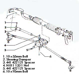
with a Steering damper, Audi 4A0 425 021. On the 1987 5000T and 1989 200TQ I looked at, the right side (passenger) mounting bracket for this steering damper is already installed from the factory as it was part of the steering rack mounting bracket welded to the frame. Here is a diagram of the steering damper installation on the 1991 200TQ to represent how this damper is installed in the earlier Audis.
You need two new bolts, two 15mm spacers, one nut, and the steering damper to retrofit this damper to the earlier vehicles. The spacers go between the damper and the right side and center mounting bracket.
You may want to use a 10mm 1.5 thread pitch tap to clean out the right side frame bracket nut threads, as it can have paint and dirt inside the thread area which will make installing the new bolt more difficult. The wiring harness may need to be moved back slightly to view this frame bracket mounting bolt hole.
The original center bolt/nut is removed by steering the car to the extreme left and then bending over the retaining metal tab on the bottom of the bracket, and then loosening, removing the nut/bolt. The stationary end of the steering damper gets installed to the right side (passenger) frame bracket using the 55mm long bolt and 15mm thick spacer between the damper and the frame bracket. The movable end of the damper bolts to the top of the steering rack center bracket with a spacer between the bracket and the damper end. The longer 95mm bolt is installed from the bottom up through the bracket, spacer, damper end and then use the new nut. The bolt/nut is should be torqued to 30 ft lb. The right side bolt should also be torqued to 30 ft lb.
AFTER YOU FINISH TORQUING THE CENTER BOLT/NUT, MAKE SURE YOU BEND OVER THE METAL TAB ON THE BOTTOM OF THE CENTER BRACKET TO PREVENT THE CENTER MOUNTING BOLT FROM DROPPING DOWN IF THE UPPER NUT COMES LOOSE!
BENDING THIS TAB OVER THE TOP OF THE BOLT HEAD IS CRITICAL TO ENSURE SAFE STEERING OPERATION!
LOSS OF VEHICLE CONTROL COULD OCCUR IF THE STEERING RACK IS PREVENTED FROM MOVING IF THIS BOLT DROPS DOWN AND WEDGES AGAINST THE TRANSMISSION HOUSING.
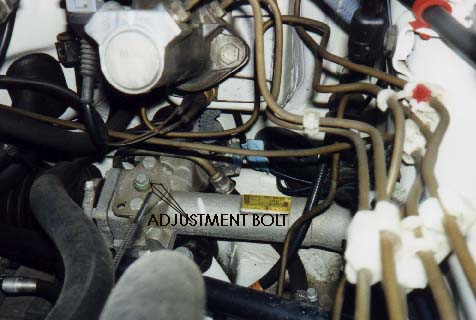
STEERING RACK PRELOAD ADJUSTMENT
If you feel excessive play in the steering wheel, or if you hear some strange rattling or popping sounds when turning the steering wheel, or if your car tends to jump right or left whenever you hit a rut or groove in the road, there is one adjustment on the Steering Rack that may help. There is a 10mm bolt that sticks out of the top of the steering rack near where the steering shaft connects to the rack.
This 10mm Bolt is the rack Pre load adjustment and it can be turned in small increments to tighten up the steering response. If you have two people available, one person can turn the steering wheel back and forth from inside the car, while the helper tightens up this Pre load adjustment in small increments until no more rattling or popping sounds are heard. Turn the bolt clockwise 1/16 to 1/8 of a turn at a time until the noise goes away and then turn it an additional 1/8 turn.
Another method involves jacking up the front of the car so both front wheels are off the ground. Be sure to use appropriate jack and safety stands under the frame rails. Start the engine with the car in neutral and turn the steering wheel back and forth to the right and left stops to get a feel for how easily the wheel can be turned. Shut off the engine and then turn this Pre load adjustment bolt only 1/16 to 1/8 of a turn clockwise and then restart the car and turn the steering wheel back and forth again to check for any binding in the steering rack. Repeat this procedure until you feel some binding and then back off the adjustment bolt until no binding is felt.
Test drive the vehicle and make sure the steering wheel returns to center after initiating a turn, if not the adjustment is too tight. Back off the adjustment slightly and road test the vehicle again.
Front Suspension Bushing replacement, Subframe Bushings
If your Audi 5000T/Q or Audi 100/200T/Q has over 100k miles on it, I recommend that you have the front end rebuilt and have all the associated bushings replaced. This will greatly improve the handling and safety of the Audis and enhance the driving experience.
The steering rack pre-load adjustment should also be done, see procedure described above for details. On the 1991 200TQ 20V, the Audi V8 and on the later 1992> Audi 100/S4 you may want to check/replace the steering damper as well.
Before starting this suspension rebuilding procedure, I recommend you have the Bentley manual for your specific vehicle at your side, and you should read through the front suspension section. Disassembling a suspension and replacing components can be a VERY Dangerous process if you don't have prior automotive repair experience.
You can do this front end rebuild in several stages if you don't want to take on the whole project at once. The subframe bushings don't have to be replaced in every case, but you should replace the lower control arm bushings, the inner stabilizer bushings, and the outer stabilizer bushings. The engine and transmission mounts can also be replaced while you are in there.
Stage 1: Replace lower control arm bushings, inner stabilizer bushings, and outer stabilizer bushings. Keep in mind that the bolts holding the inner control arm bushing should only be tightened with the suspension compressed like when the wheels are on the ground. If you tighten the inner control arm bolts with the car lifted in the air, the inner bushing will be twisted and strained when the car is lowered back down on the tires. Replace appropriate hardware (bolts and lock nuts as required) Replace subframe bushings (optional) Replace rear transmission mounts (optional) Replace Engine Mounts while subframe is removed from vehicle (optional)
Stage 2: Remove Strut and coil spring assembly: Remove coil spring using approved and safe spring compressor, (use stock or aftermarket coil springs) and replace upper strut bearing and upper strut mount. Replace Strut boots, and strut bump stops (optional) Replace Wheel Bearings (optional) Replace inner and outer CV Boots, clean and repack CV Joints (optional) Replace tie rod ends (optional) Replace required hardware (bolts and lock nuts)
Parts List Stage 1:
If you decide to replace the subframe bushings, you will likely want to replace the rear transmission mounts as they can be easily replaced when you remove the subframe assembly. These rear transmission mounts can sag and get mushy from leaking power steering racks. It is also a good idea to check/replace the engine mounts when the subframe is off the vehicle.
If you have a grinding/rubbing noise when turning the wheels with the car at rest, you may want to plan on removing the front strut assemblies, compress and remove the coil springs and replace the upper strut bearings. Often times the upper strut bearing plastic dust covers get deformed and allow dirt/grit to make its way into the strut bearings.
Along with the upper strut bearings, you may want to replaced the rubber shock boots and consider having new wheel bearings pressed into the strut housings while you have them off the car. It is not uncommon for the front wheel bearings to start making noise as the mileage gets above 100K miles. The tie rod ends should also be checked for excessive play, and torn dust boots, and make sure the adjustment thread lock nuts are loosened, and clean off any rust and make sure they are well lubed to make the toe in adjustment and front end alignment easier.
If you have the original Constant Velocity (CV) Joints and the original CV boots that show signs of cracking, it is a good idea to remove the front axles, press off the inner and outer CV joints, disassemble and clean them, inspect and re-grease them, and install new inner and outer rubber boots. This is a horribly messy job that no one enjoys, but at least it ensures that a CV boot won't crack and allow the CV joint to spew grease everywhere later on down the road.
As mentioned previously, the factory repair procedure requires the replacement of the lock nuts and bolts used for mounting critical suspension components.
Basic Instructions, Always consult your vehicle specific Bentley Repair Manual: If you are going to clean and repack the Axle inner and outer CV joints, and replace the CV boots, you will want to loosen the front axle outer nuts or bolts with the wheels still on the ground.
You may also need to loosen the inner CV bolts before you jack up the car, unless you have access to an air driven impact gun. Make sure you clean out the CV joint bolt heads first, before inserting the triple square 10mm drive bit to loosen them, otherwise you can strip out the head of the bolt and make your life miserable. A sawsall equipped with a metal cutting blade can be used to cut off the bolt head in cases where the bolt head inner spline gets stripped.
After you raise the vehicle off the ground and safely support the vehicle with appropriate jack stands, you can remove the front wheels.
Replacing the inner control arm bushings, inner and outer sway bar bushings:
If you are only replacing inner control arm bushings and the inner and outer sway bar bushings, it is usually easier to first remove the sway bar, then remove the lower control arms. Remove the two large nuts and washers at the left and right sides of the sway bar where the bar goes through the lower control arm. Now remove the 4 bolts/nuts on the 2 front sway bar bushing clamps to allow the sway bar to hang down without tensioning the lower arms. A box 19mm wrench works well for the one bolt pointing downward, a 19mm open end wrench can be use to get the other nut on top. Remove the inner control arm bolts and nuts. The right side top nut can be held with a short 19mm socket on a flex handle while you spin loose the bolt from below. The loose bolt can be left in the control arm for the moment.
Loosen the ball joint retention nut, the original nut uses a 17mm socket, the replacement nuts require a 16mm socket or wrench. Now you can wrestle out one of the sway bar ends from one of the control arms by pushing back the strut assembly with your foot while holding up the sway bar and then remove the other end of the sway bar from the other control arm.
Now you can remove the lower control arms, with the ball joint pinch bolt nut removed, you can usually tap out the bolt with a small punch and hammer. You may need to spray some penetrating fluid around the ball joint shaft if excessive rust is present. With the pinch bolt removed, you can use a long 3-4 foot bar between the body area behind the control arm, and against the control arm to pry downward and pop loose the ball joint shaft from out of the strut housing. Be careful not to damage the CV boots if you are not replacing them at this time.
DO NOT SPREAD THE STRUT HOUSING APART WHERE THE BALL JOINT SHAFT IS LOCATED.
USE CAUTION, TO AVOID TEARING THE BALL JOINT RUBBER DUST BOOT.
These rubber ball joint boots are available separately should you destroy one, but they are costly.
After you get one side of the lower ball joint popped out you can pull the control arm to the rear and then remove the inner control arm bolt and pull the control arm out of the subframe area. You should have new lower control arm bushings pressed in by your local machine shop. The lower control arm bushings are very important to replace, as they are crucial to maintaining stability of the strut assembly. These lower control arm bushings have a thin outer metal sleeve and can be difficult to press in, if you don't have the correct sized press tool.
If you are only replacing the inner control arm bushings, and sway bar bushings, you can CLICK HERE to skip down to the installation details.
If you are replacing the subframe bushings, CLICK HERE
FRONT AXLE REMOVAL, OUTER AND INNER CV JOINT BOOT REPLACEMENT
It is a good idea to first remove the ABS sensor from the strut housing if you are pulling the axle and outer CV Joint. The 1986-88 Audi 5000/T/Q use an allen screw to retain the ABS sensor in place. Remove the allen screw and then withdraw the sensor from the strut housing.
The 1989 and later Audi 100/200/S4/S6/A6 use an ABS sensor that is pushed in place and retained with an outer spring collar. This type of ABS sensor can be carefully pried out of the strut housing, using wide blade screw driver while you pull the sensor head out with your hand.
In order to remove the axles to replace the CV boots, you can now remove the outer axle nut/bolt completely, as well as removing the inner CV joint bolts (6).
The 1986-88 Audi 5000 vehicles and Audi 100's (Front wheel drive) have front outer CV Joints with a long threaded axle and lock nut, and these require that you remove the ball joint retaining bolt/nut and pop the this lower ball joint out of the strut housing to allow enough room to remove the front drive axles from the strut housing/hub. Turning the strut housing all the way out left or right as needed, gives additional room to allow getting the axle stub from out of the strut housing.
The 1989 and later 100/200/S4/S6/A6 quattros have a different outer CV Joint with a shorter outer stub axle that uses a long bolt to retain this CV joint in the hub. You can usually remove the front axle assemblies after removing the inner CV Bolts, and the outer CV Bolt, by pivoting the strut housing all the way out to the right or left. Then raise up the inner CV Joint to allow enough room to get the outer axle stub out of the front hub/strut.
All vehicles: You may need to use a soft punch and hammer to tap out the CV joint/axle shaft assembly from the hub splines in the strut housing.
After you have the complete axle assembly out of the vehicle, you can remove the inner CV Joint by removing the C clip and then you can cut off the old inner CV boot and use a punch and hammer to tap off the inner CV joint "inner" race off the axle. Then install a new inner CV boot, clean and repack the inner CV joint and tap it back onto the axle and install the new C clip. Removing the outer CV joints from the axle can be a pain, the 1986-91 Audi 5000/100/200 require you to spread apart a C clip with some snap ring pliers where the outer CV Joint inner race meets the axle , while driving the inner joint race off with a punch and very large hammer. 2 people can make this easier, one to spread the C clip, the other to drive off the inner race.
FRONT AXLE ONLY: The 1992 and later Audi 100/S4/A6/S6 have an outer CV Joint which uses an inner retaining clip that is not accessible from the outside. These require the use of a threaded tool Audi # 3207 or a long 16mm threaded bolt to pop the outer CV Joint off the axle. See the Bentley manual section for details. Note: The rear axle outer CV Joint uses a C clip (snap ring) to hold the inner race to the axle, the outer CV boot should be removed, and then this C clip needs to be spread apart before attempting to drive off the rear Outer CV Joint with a punch and hammer. In some cases if you have an old outer axle hub bolt (16x1.5x77 mm) that is threaded all the way up the bolt, you can use this bolt to thread into the end of the CV Joint axle stub and pop the outer joint off the axle.
A hydraulic press and a long bolt or punch can be used down inside the axle stub to push off the main axle from the outer CV Joint.
If you have trouble with this, you may want to take the entire axle assembly to a Audi/VW shop and have them do the CV joint repacking and installation of the new CV boots.
REMOVING THE STRUT ASSEMBLY If you are removing the entire strut assembly, on some vehicles you will need to remove the horse shoe shaped clip, holding the brake hose to the strut housing, in others there is a rubber grommet holding the hose to the strut, then unbolt the caliper assembly from the struts and hang the caliper up with some coat hanger wire or other suitable wire to avoid damaging the brake hose.
Remove the ABS sensor from the strut housing, either by unbolting the retaining allen bolt on the 5000T/Q vehicles, or by using a wide bladed screw driver to pry out the sensor on the 100/200T/Q and S4/S6 model vehicles. Be sure to remove the ABS sensor cable from the retaining grommet on the strut housing, and tie the sensor and cable out of the way to avoid damaging the sensor.
Now remove the tie rod end from the strut steering arm. First, you should loosen the tie rod end adjusting nuts on the tie rod. You may need to use some penetrating oil, or some heat to break these loose. One of the nuts will have left hand threads, so you will be turning it clockwise to loosen it. The best way to remove the tie rod ball joint from the strut steering arm, is to use a large heavy duty ball joint or tie rod puller. You first remove the nut on the tie rod ball joint shaft, and then use a tie rod or ball joint type puller threaded bolt to press up the tie rod ball joint shaft.
WEAR EYE PROTECTION One other method that works well if you don't have the puller, and you intend on replacing the tie rod ends (recommended), is to take a 5 or 10 lb sledge hammer and rest it on the outer edge of the steering arm, just in front of where the tie rod goes through the arm. Now use another (large) hammer from below and whack the tie rod joint upward to pop it loose. (Make sure you remove the tie rod nut first) If you hit the tie rod joint hard enough, and support the steering arm with the heavy sledge hammer, it should pop loose. Just make sure you don't beat the daylights out of the tie rod end, until it mushrooms out and prevents it from coming out of the steering arm.
An air driven hammer tool and sharp pointed driver tip can also be used to drive the tie rod end out with the sledge hammer resting on the steering arm. The pickle fork type tie rod removal tools can also be tried, to attempt to wedge between the arm and the tie rod ball joint upper cap, but I have not had very good luck using this air driven pointed tool on the Audis as the tie rod can be wedged very tight into the steering arm.
After you get the tie rod loose, as well as the front axle outer CV joint, and the lower control arm, the entire strut/coil spring assembly can be removed from the car and disassembled so you can replace the upper strut bearings and top strut rubber mount.
You may want to remove the disc brake dust shields, first, to avoid smashing them or denting them while handling the strut assembly.
There are 3 nuts/washers that need to be removed from above, to allow the strut to drop down.
THE STRUT ASSEMBLY IS VERY HEAVY, SO BE READY TO HOLD IT UP AFTER YOU REMOVE THE TOP NUTS.
You should measure or mark the location of the upper strut mount relative to the top strut plate, and relative to the body to return the car back to an approximate alignment setting. (Camber).
With the strut assembly out of the car, before disassembly, you should first mark the location of the upper end of the coil spring, the upper strut mount and plate relative to the lower strut assembly, so you can have the coil spring and upper plate/mount orientated correctly when you reinstall the strut assembly back into the car.
Now you can compress the coil spring with an appropriate and "safe" automotive Coil spring compressor, and then you can remove the top shock (strut insert) nut. A 6 or 7mm allen wrench is typically needed with a 7/8 inch or appropriate size wrench to loosen this top shock nut.
The upper strut bearing should be replaced, it is located underneath the top plate, sandwiched between the lower coil spring rubber mount plate. The upper strut/shock mount with the slotted holes should also be replaced as these rubber bushings can tear on the inside edge. The mounts for the 1986-90 5000/100/200 are pretty inexpensive, but the ones for the 1991 200TQ 20V are unique, and can be expensive. The later 1992-95 S4/S6 forged upper strut mounts are available in the aftermarket, so they are not too expensive.
You should also inspect the rubber coil spring Damper Ring, and the plastic dust shield, and replace these items if they are smashed/squashed or deformed enough.
If you replace the plastic dust shield, you may also need to replace the lower metal ring that the dust shield clips on to, as on some vehicles, these parts have been superseded, and must be replaced together.
If you replace the shocks/strut inserts, you can use the Audi Tool 2069 to loosen the cap nut holding the shock/strut insert inside the strut housing. Bilstein shocks use their own unique tool for removing this top cap nut. If you are desperate and don't have the correct tool for loosening this cap nut, a large pipe wrench or some very large channel lock pliers can be used to loosen this nut.
Follow the strut (shock) manufacturers installation instructions. Some strut inserts have a unique retaining collar that goes on top of the strut insert, before you screw the cap nut on.
BILSTEIN STRUT INSERTS: Most Bilstein front strut inserts have internal bump stops that don't require the installation of the OEM type external bump stop on the shaft of the strut. Also note that with Bilstein strut inserts, you DO NOT want to install any oil or liquid into the bottom of the strut housing, clean out any existing oil or liquid from the strut housing before installing the Bilstein struts.
I also recommend that you have new wheel bearings pressed into the strut housing while you have the front end apart, these bearings often will start making noise as the car gets over 120-150k miles, so it often makes sense to replace them now. A hydraulic press and some correct sized bearing/strut support tools are required to replace these bearings, most machine shops can do this press work for you.
After installing the new wheel bearings and the strut inserts (if needed), the new shock boots (where applicable), coil spring and upper strut bearings and mounts with strut insert shaft nut, you can re-install the strut assembly into the body using the existing washers and new lock nuts.
The axle outer CV Joint stub can be carefully inserted into the strut assembly and you can thread the outer nut or bolt to retain the axle into the hub area. Install the new tie rod end with new lock nut torqued correctly.
Install the ABS sensor, the earlier 1986-88 Audi 5000 vehicles require a new plastic cap over the ABS sensor tip to correctly locate the tip into the strut housing. The later vehicles use a spring clip to hold in the sensor, the sensor is normally just pushed in as far as possible and bottomed out against the CV axle hub teeth, then the spring clip pulls back the sensor tip slightly. Re-install the ABS sensor cable clamps, install the brake disc (rotor) and brake caliper and brake hose grommet or clip as needed.
Note: Some repair shops have a threaded special tool that can replace these wheel bearings with the strut installed in the car.
On high mileage vehicles, over 120-150k miles, I recommend that you replace the subframe bushings when you are doing the rest of the front end rebuild. To replace the front suspension subframe bushings. I normally remove the entire front subframe to replace the bushings. You need to support the rear end of the transmission with a jack stand, and then remove the bolts for the rear/side transmission mounts. There is a small heat shield on the passenger side trans mount that needs to be removed to gain access to the trans mount bolt on that side. This heat shield is held on with three screws (8mm head size).
After removing the rear trans mounts (two 13mm hex head bolts/nuts), remove the 4 large bolts holding the subframe to the vehicle frame and then carefully lower down the subframe. (it weighs a bit, so be careful).
With the front subframe out of the car, you may also want to replace the hydraulic engine mounts, as they are a little easier to get to, with the subframe removed. I also recommend that you replace the rear transmission mounts at this time.
1984-91 Audi 5000/100/200 SUBFRAME BUSHING REPLACEMENT Once the subframe is removed from the car, use a drill and appropriate drill bit to drill out the rubber on the inside of the rear subframe bushings, then I use an air chisel or chisel and hammer to collapse the outer metal sleeve on the bushing to allow it to be popped out of the subframe using a hammer and socket.
A bench vise and a couple of large sockets can be used to press the new rear subframe bushings back in. Use one socket to support the back of the subframe, and another socket around the bushing end to push in the metal edge. Handling the subframe while holding the sockets/bushings can be a handful, so having a helper assist you can be a big help.
1984-91 Audi 5000/100/200: Make sure you orient the subframe bushings correctly, with the two slots pointing along the longitudinal axis (front to rear) of the subframe respectively.
The Bentley manual shows this important detail.
To remove the Front subframe bushings, I carefully cut off the thick rubber lip with a razor knife, and then just push them out with a socket/hammer. Pressing them in can also be done with a bench vise, be sure to use a 1/2 inch diameter or equivalent socket and press on the small inner sleeve to stretch the thick rubber end of the bushing outward to allow it to pop in place and be retained by the rubber lip. If you try and press on the outer metal sleeve area, you will have a rough time getting these in.
SUBFRAME INSTALLATION:
Installation of the subframe is the reverse of the above procedure for the most part but note the following:
The Subframe bolts should always be replaced (stretch type of bolts) whenever they have been loosened or removed. They should be torqued and tightened as detailed in the Bentley repair manual. Some vehicles also have a specific sequence to adhere to when tightening each one of the subframe bolts.
Before torquing and tightening the subframe bolts, note that there is a specific sequence described in the BENTLEY manual that should be used when tightening these bolts.
Also note that subframe position can be shifted slightly from side to side to adjust the alignment camber and caster setting for each side of the vehicle. In order to ensure that each side has the same camber adjustment range, you may want to drop a plumb bob line from the upper strut mount bolt/nut and measure from this line to the lower control arm inner bushing location to get the alignment camber settings even on each side of the vehicle.
INSTALLATION DETAILS: The most important thing to remember when you are putting the front end back together, is that there is a specific sequence and procedure for tightening the subframe bolts. See the Bentley manual for details.
NOTE: You should NOT fully torque the Axle nuts/bolts, the lower control arm bolts, and the front stabilizer bushing inner and outer nuts/bolts, UNTIL the car is resting on the ground on all 4 wheels/tires. The car should be bounced around to settle the suspension first, then crawl underneath and torque the nuts/bolts to the correct values.
You want to make sure the bushing retention bolts/nuts are not tightened with the wheels off the ground, as this would put the rubber bushings under a strain when the car is on the ground, and will cause early failure of the bushings.
The Audi 200's and S4/S6's use a large shouldered bolt to retain the axle bearing/Hub/CV joint, and this bolt must be replaced anytime it has been loosened. The earlier Audi 5000's used a large lock nut which also must be replaced any time an outer axle is removed.
INSTALLING THE LOWER CONTROL ARMS: With the subframe and strut assemblies installed, as well as the brake rotors and calipers mounted back in place, you can now install the lower control arms with the new inner bushings. Be sure to clean out the subframe area where the lower control arm inner bushing is mounted, this area often gets full of dirt and rocks. Insert the bolt with washer from below into the subframe and inner control arm bushing, and install the upper washer and new lock nut Use a 16mm socket to hold the upper nut while you tighten up the bolt several turns to hold the assembly together, but don't fully tighten this bolt/nut yet.
Now you can pivot the strut assembly outward slightly and insert the ball joint shaft into the hole in the strut housing. Getting the ball joint shaft lined up is a little tricky, as it can get cocked sideways and get stuck in the hole. Try and line up the shaft with the correct angle before you try and insert it into the strut housing hole. Once you get the ball joint shaft lined up correctly, and partially installed into the hole, you can use a small hammer to "gently" tap the ball joint shaft completely into the strut housing. The shaft should easily move into place if it is lined up correctly, you don't want to hammer very hard on the bottom of the ball joint. Tap the ball joint shaft into the hole until you can insert the new ball joint retention bolt from the rear. Now install the new lock nut and torque this ball joint retention bolt/nut as specified in the Bentley manual for your vehicle. Repeat the installation of the control arm for the other side.
SWAY BAR INSTALLATION: Now you can install the sway bar, you will first want to install 2 of the new outer sway bar bushings on each end of the threaded bar before inserting each end into the lower control arm holes. With one end of the sway bar into the control arm on one side, you may need to push back the strut housing on the other side to allow getting the sway bar into the control arm.
Use a small floor jack to hold up the front of the sway bar while you install the new inner control arm bushings around the sway bar, push on the metal clamps around these inner bushings.
Move to the outer ends of the sway bar now and use some very large pliers or some brute force to push on each outer end of the sway bar to allow installing the other 2 new outer sway bar bushings, washer and get the new lock nuts threaded onto the ends. Thread these new lock nuts on several turns to hold the outer ends of the sway bar into the control arms. If you can get the outer bushings into place without pinching them you can tighten the outer nuts several more turns.
Now you will need to push up the front of the sway bar into place using the floor jack and a pry bar to get the inner bushings located into the recess in the subframe. Make sure the inner bushing mount upper bolt/washer is inserted down into the subframe to help locate the bushing clamp as you push it up into place. The rear part of the inner sway bar bushing has a tendency to get pinched and bulge out of place, so you may need to pry the sway bar forward, or use some large pliers to help push the clamp into place around the inner bushing and force it into place onto the subframe recess. Install the 4 new lock nuts with the original washers above and below the inner bushing mounts, and partially tighten these nuts/bolts as you watch carefully so that the bushing rear section is drawn up correctly into the recess in the subframe. Don't fully tighten these 4 nuts/bolts yet.
With the entire front end back together including the subframe, axles, strut assembly, brake calipers, lower control arms, sway bar etc. you can install the wheels/tires and lower the vehicle down onto the ground. Bounce the suspension up and down to settle the suspension position so you can do the final torquing of the inner control arm, inner and outer sway bar mount bolts/nuts, as well as the torquing the large axle nuts or bolts.
In some cases you can lower the tires onto some 4" X 10" long blocks of wood to give some additional clearance under the car to allow torquing these bolts/nuts. The wheels can be turned in or out to allow reaching the outer sway bar lock nuts for torquing.
Have the car aligned professionally, for stock suspension I like to have the camber set to -0.5 degrees at all four wheels if possible. Lowered vehicles often end up with front camber settings close to or exceeding the -1.0 degree factory limit.
Mounting Wider Wheels and Tires on 1986-88 5000T/Q and on 1989-90 200TQ?
The following information should be used as a guideline, and not any sort of absolute fitment recommendation. Any aftermarket wheel and tire you want to use, should be test fitted for clearance, as different manufacturer tires, along with body/suspension assembly tolerances can change the ability to mount specific wheel/tire combinations.
Keep in mind, that the original equipment (OE) tires and wheels were chosen by Audi to provide a good compromise in ride quality, resistance to hydroplaning, and all weather traction. Wider tires will be more susceptible to hydroplaning, all else being equal.
The 1986-88 5000T/Q and on 1989-90 200TQ vehicles which came with 5 bolt, 112mm spacing wheels, and without flared fenders, can be tough to mount aftermarket larger diameter, wider wheels with wider tires, due to clearance problems in the rear fender lip and the front steering arm.
The stock wheels used were 15X6 inch wheels with 45mm offset. There were also some optional forged 15X7 inch Fuchs wheels available with 45mm offset.
A wheel with a 45mm offset, has a center line that is located closer towards the inside of the wheel well, when compared to a wheel with 35mm offset which has a centerline located 10mm further outside the wheel well.
There are some factory original equipment 5 bolt, 112mm spacing, 16X7 inch wheels with 45mm offset which were used on the later Audi A6 and Audi A4 vehicles which will bolt onto these 1986-88 5000T/Q and on 1989-90 200TQ vehicles along with 205/55X16 inch tires without clearance problems. Many times these factory wheels are available as "take offs" when a Audi A6 or A4 owner upgrades his wheels to 17 inch diameter. Note: Some of the factory Audi A8 16X7 inch Five spoke wheels look identical to the A4 16X7 inch, Five spoke wheels, but have a 37mm offset which may not work.
When mounting larger diameter and wider aftermarket wheels (16X7.5 or 16X8 inch), the problems occur when trying to mount these wheels which have a 35-38mm offset, because of tire clearance problems at the rear fender outer lip. This is true when using 205/55X16 tires, and it gets even worse when trying to mount the wider 225/50X16 tires. For adequate tire clearance, the rear wheels used should be closer to the stock 45mm offset or if this offset is not available, some flaring of the rear fender lip will be required. Unfortunately, most aftermarket wheels come with this 35-38 offset, as this range of offsets will typically work on the 1991 and later Audis with flared fenders.
The fronts can have a clearance problem if the 16 inch wheel offset is too close to the original 45mm offset and the wider 225/50X16 tires are used, as the inside edge of the tire can hit the front steering arm on the strut.
For example, this is the case when the OE Audi S4 16X8 inch wheels with 40mm offset and 225/50X16 tires are mounted on the front, the inside tire edge will usually rub against the steering arm and prevent using this combination. In the front, a wheel with the 35mm offset works better, as it is located further out, away from the mounting hub/strut steering arm assembly.
Some 1986-88 5000T/Q and on 1989-90 200TQ vehicles owners have had success mounting a 16X7.5 inch aftermarket wheel with 42mm offset and 205/55X16 tires, in the front and rear without any clearance problems, or the need for rear fender flaring. The tires just barely clear the fenders!
Others have gotten some additional clearance in the rear by setting the rear camber, to a more negative setting, i.e. more than the stock negative 1/2 degree. In some cases they run up to 1.5-2.0 degrees negative camber.
Still others, have used different offsets in the front and rear wheels to mount the largest wheel/tire available. Usually they have a wheel with a 45mm offset mounted in the rear, and use a 30-35mm offset wheel mounted in the front.
One other example: my 1989 200TQ currently has 205/55X16 tires, mounted on TSW aftermarket 5 bolt, 112mm spacing, 16x7.5 inch wheels with a 35mm offset, but I did have to flare out the rear fender lips by 3/8 inch for adequate tire clearance. The front tires may rub on the outer edge of the plastic fender liner, if the liner mounting screws are missing.
Flaring out the rear fender lip can be very tough to do, without cracking the paint, or buckling the fender, as this fender area has a inner liner and welded seam that are very stiff and resist movement.
CAN the S4 16 X 8" WHEELS FIT A 1991 200TQ with flared fenders?
A local Audi enthusiast is using the 16 X 8 (40mm offset) 5 spoke S4 wheels on his 91 200TQ 20V with the factory flared fenders. He is using OEM S4 size tires, 225/50 X 16 D40 M2 tires. He does not have any clearance problems.
FYI: I did check the fit of these wheels and tires on my 89 200TQ and the front tires rub against the steering arm in the front and the rear tires outer edge will definitely rub against the outer lip on the fender. The same fitment problem will occur on the 1986-88 5000T/Q vehicles.
On my modified 1987 5000TQ track car, I run these S4 wheels with 245X45X16 Kuhmo Victor Racer track tires with 8mm spacers up front and some fender lip adjustments, and in the rear with heavy fender lip flaring modifications.
Can the Flat Face 6 spoke alloy wheels from the 1984-85 5000 Turbo and early 1986 5000TQ, fit the later 1986-88 5000TQ The 84-85 5000 Turbo and early 1986 5000 Turbo and Turbo Quattro vehicles did not use the dual piston G60 calipers and this also means that the Flat Faced 6 spoke alloy wheels that came on these Audis are slightly different on these early cars than on the later 86-88 5000T/Q. In mid year 1986 they changed these wheels slightly to allow more inner clearance between the wheel rim and the new G60 brake caliper they started using.
These Flat Face style Six spoke wheels are NOT the light weight 5 spoke Fuchs style wheels that were optional on these 1986-988 5000T/Q vehicles.
The early wheels from the 84-85 5000T that I have use a part number of 447-601-025B, but the later wheels that came on my 88 5000TQ have a 447-601-025 "D" part number. I fitted the early wheels on the later 1988 5000TQ car with the G60 calipers and there is very little clearance between the caliper and the inner part of the wheel, looks like less than 0.050 inches of clearance. The later wheels have more like 0.150 clearance. Under hard braking it "may" be possible for the G60 caliper to interfere with the early wheel as the caliper flexes. You also want to keep any stick on balance weights away from this area inside the wheel that rotates around the caliper area.
Copyright © SJM Autotechnik™ , all rights reserved
Return to Troubleshooting Tips page. Return to SJM Autotechnik™ main page.
|
|||||||||||||||
| About Us Privacy Policy Terms of Use Links Customer Service Safety Information Home |