ECU System,
1986-90 5000/200TQ:
Oxygen (O2) Sensor, Open Loop and Closed Loop Operation
Testing the O2 Sensor
Testing O2 with DMM
Testing O2 with Oscilloscope
Sensor Problems
Basic Operation Details:
The oxygen sensor is mounted in the exhaust pipe just after the turbo
exit.
The O2 sensor has a internal heating element to ensure quick warm up
and correct operation at idle. There are three wires going into the
O2 sensor on the Audi Turbos. One ground, one +12V signal, and one for
the actual O2 sensor output voltage.
If you have trouble with the O2 sensor working correctly at idle, the
heating element inside the sensor may be defective. The fuel pump relay
supplies +12V to this sensor and to other engine solenoids through circuit
87a, you should check for +12V and ground across the two terminal connector
to the O2 sensor with the engine running.
You can also check the heater inside the O2 sensor by disconnecting
the two terminal connector for the O2 sensor heating circuit, and then
measure the resistance across the O2 sensor heating element, it should
read around 5 ohms, but this resistance will vary a little as the sensor
warms up. The resistance will read open circuit (infinity ohms) if the
element is burned out.
The sensor heating element draws 1.7 amps when first energized, the
current will drop to around 1.0 amps after the heating element gets
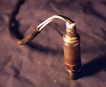
warm. The O2 sensor incorporates a vent to outside ambient air for a
reference to compare to the oxygen level in the exhaust gas.
This vent is normally in the area where the wires exit the sensor, so
be careful not to get water or other debris in the top of the O2 sensor
when cleaning the engine. Here is a picture of the O2 sensor with it
removed from the exhaust down pipe.
When the engine is first started when it is cold, the engine will briefly
run for 1 or 2 minutes in open loop operation based on the "basic" idle
mixture setting in the CIS Fuel Distributor/Air Flow Meter assembly
and by the duty cycle programmed into the ECU.
Normally the basic idle mixture is set to be 0.6% to 1.2% Carbon Monoxide
(CO) when the exhaust gas is measured up stream of the catalytic converter.
Once the Oxygen (O2) Sensor warms up (Heated O2 sensor), the system
will switch over to closed loop operation.
This sensor is used to monitor oxygen levels in the exhaust and acts
as a voltage supply that transitions high to low when the oxygen level
is high (slightly lean above 14:7 to 1 air fuel ratio) and transitions
low to high when the Oxygen level is low (slightly rich air fuel mixture
below 14:7 to 1 air fuel ratio).
The ECU uses this oxygen sensor signal to tweak the air fuel mixture
back and forth close to the ideal 14.7 to 1 Air Fuel Ratio. With the
fuel system in closed loop operation after the O2 sensor warms up, the
O2 sensor voltage cycles up and down between ~0.1V and ~0.9V.
At idle, the O2 voltage should cycle back and forth 1 to 2 times per
second and when cruising, it should cycle back and forth ~4 to 5 times
per second. This cycling occurs because the engine computer senses the
O2 voltage and then changes the duty cycle going to the CIS Frequency
valve (Mixture solenoid).
This Frequency valve alters the lower chamber pressure in the fuel distributor
which alters the fuel flow out to the injector. This switching action
allows the ECU to do minor adjustments to the air fuel ratio to allow
the catalytic converter to perform its job to optimize the "oxidation"
of Carbon Monoxide (CO) and Hydrocarbons (HC) and the reduction of Nitrogen
Oxides (NOx).
The oxidation occurs when the mixture is slightly lean and more oxygen
is available, and the reduction occurs when the mixture is slightly
rich and less oxygen is available. These chemical reactions that occur
in the catalytic converter ensure the lowest possible emissions out
the tailpipe. Catalytic converters typically operate at 60-90% efficiency
depending on age.
This means that the amount of exhaust emissions that enter the catalytic
converter are reduced approximately by this percentage. For example,
in the Audi I5 turbo engine, at idle, you typically have exhaust gas
entering the catalytic converter with a Carbon Monoxide (CO) level of
1.2%, this will be reduced to ~ 0.36% to as measured at the tailpipe
with a 70% efficient converter.
Here is a chart showing the relationship between the various exhaust
gases and air/fuel ratios.
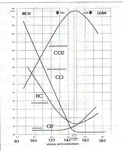
Diagram courtesy of MPSI Emission Control Training Manual
You can watch the Frequency valve duty cycle change back and forth on
an oscilloscope screen and if you connect up the O2 voltage signal on
channel 2 and the frequency valve signal on channel 1 of the o-scope.
You will see how the high (rich) O2 voltage will cause the frequency
valve duty cycle to be reduced in order to lean out the mixture.
NOTE: If the Oxygen sensor or wiring fails, the ECU will use a 50% duty
cycle to operate the frequency valve.
O2 SENSOR - TESTING
If the O2 sensor wire is disconnected with the engine running, the ECU
normally has a 0.450 V (+/- 0.050V) reference voltage on the ECU wire
connecting to the O2 sensor.
The ECU will switch over to a basic idle mixture setting (frequency valve
duty cycle set to 50%) with the O2 sensor disconnected. If you suspect
the O2 sensor is causing a running/drive-ability problem, you can temporarily
disconnect the sensor and drive the car to see if the problem still exists.
The system is designed to operate without the O2 sensor connected and
the engine will run fine assuming the other systems/components are functioning
properly and the basic idle mixture is set correctly (upstream idle mixture
CO% is set between 0.6% to 1.2%).
Please note that disconnecting the O2 sensor will store a fault code in
the ECU. The ECU O2 signal wire is the large green wire with male and
female spade connector under the small rubber boot.
The 1986-88 5000 Turbo and 5000 Turbo Quattros have this O2 sensor green
wire and rubber boot over the connector laying along the right fender
lip and the fuel distributor/air flow meter assembly. The later 89-90
200T/Q with the dual knock sensor MC engine have this rubber boot connection
on the back engine firewall area on the bracket with the other color coded
connectors.
DMM TESTING
You can also use a Digital Multimeter (DMM) to do a basic test of the
O2 sensor voltage with the sensor connected to the ECU, but the meter
normally will not respond quickly enough to see the voltage go up and
down. It is important to know what the input impedance is of the meter
you are connecting across the O2 sensor or for that matter across any
of the ECU inputs/outputs.
Most modern DMM's have a 10 Mega-ohm input impedance. Many of the older
analog meters have a input impedance down below 100K ohms. These older
meters "may" work once your O2 sensor is warmed up as the impedance of
the O2 sensor usually drops to 5-20k ohms.
If your DMM has a "analog" type bar graph feature, you can measure the
O2 voltage and see changes, as this bar graph display responds quicker
and this can be used to monitor the O2 sensor voltage as it swings high
and low when the ECU/fuel system is in closed loop operation. If the DMM
has a "zero" feature to zero out the bar graph reading with a voltage
applied, you can connect the DMM to the O2 sensor wire and turn on the
ignition before starting the warm engine.
The DMM should read ~0.45V with the meter connected to the O2 sensor wire
with the ignition on, but with the engine not running. Now zero out the
0.45V reading, and start the engine. The DMM bar graph should oscillate
up and down around this 0.45V reference voltage 1 to 2 times per second,
indicating that the system is in closed loop operation.
OSCILLOSCOPE TESTING
One test you can do with the O2 sensor wire connected to the ECU, is to
use an oscilloscope to measure the O2 sensor voltage and then force the
mixture rich with the slow addition of propane into the intake system.
The O2 sensor voltage should rise up to at least 0.85 volts. Then force
the mixture lean by creating a huge vacuum leak and measure the O2 voltage
transition time when the voltage drops from high to low.
To quickly force the mixture lean, you can pull off a large hose from
the intake manifold, or remove the oil cap from the valve cover (10V Turbo
only). This will make the engine stall but you can capture the O2 voltage
response on the digital oscilloscope.
Typical transition times are around 25-50ms, the rule of thumb is that
the O2 sensor transition time from 0.6V to 0.3V or from 0.3 to 0.6V should
be under 100ms. The O2 sensor will have a different transition time going
from rich to lean than from lean to rich, if I remember correctly the
rich to lean transition is slightly longer.
It is important to understand that if the VAG1552, the DMM, or the Oscilloscope
shows the O2 sensor voltage stuck high or low and not oscillating up and
down, that the sensor may be working correctly. The real problem may be
mechanically related (lean condition from vacuum leak) or engine fuel
system may have a problem (rich mixture from fuel pressure being too high).
When the engine is running very lean (low O2 voltage) or is running very
rich (high voltage) the ECU can not tweak the mixture enough to compensate
for these problems. The O2 sensor heating element could also be defective,
and this can cause a cold O2 sensor at idle with no fluctuation in output
voltage. O2
SENSOR PROBLEMS
One problem that affects the O2 sensor operation is contamination or
poisoning by silicone, this shows up as a fine white powder on the tip
of the sensor and will reduce the voltage output of the sensor when
the mixture is rich, and this will cause a loss of fuel economy and
increased CO and HC emissions. You may also see a negative voltage developed
under lean operation when the sensor is poisoned by silicone. This poisoning
causes the sensor to see a lower proportion of Oxygen.
The slots in the tip of the O2 sensor can also get partially clogged
with carbon which will increase the response time. This will cause the
O2 voltage change to slow way down, taking 3-4 seconds to go up and
down, instead of changing in less than a second. This slow response
can cause a varying idle speed and varying idle mixture.
The exhaust gas Carbon Monoxide (CO) reading will not be steady at idle
when read by an exhaust analyzer. This can also cause some light surging
under light acceleration with the engine cold and when fully warmed
up under cruise conditions.
There are several Society of Automotive Engineers (SAE) articles that
have been published since the early 70's that describe in the utmost
detail the operation of these O2 sensors.
Here is a photo showing some details on the O2 sensor construction.
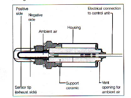
Diagram courtesy of Robert Bosch Corporation
Here is an excerpt from the 1976 SAE article #760287
"Closed Loop Control of Lean Fuel-Air Ratios using a temperature compensated
Zirconia Oxygen Sensor"
"The sensor is based on the electro-chemical potential developed across
a zirconium dioxide solid electrolyte when its two electrodes are exposed
to differing oxygen concentrations. One electrode is exposed to the
constant oxygen pressure of ambient air and the other to the oxygen
pressure of the exhaust gas which varies with equivalence ratio.
A voltage is produced which is a function of the equivalence ratio."
Most university libraries have the articles going many years back on
micro-fiche and they should have an index that lists all the articles
by subject, author and number.
Go to O2 Sensor and Emission Article
Listing for details.
Bosch Replacement 3 Wire Oxygen Sensor
Bosch makes a replacement 3 wire O2 sensor which is sold in large quantities
and carries a reasonable price. This generic O2 sensor can be used in
the Audis if you use your original wiring and connectors and splice
it to the wires on the new oxygen sensor.
Universal O2 sensor and O2 sensor with harness
I use the smaller gauge (red) butt type crimp connectors to splice
the original O2 sensor wiring to the new generic O2 sensor.
I cut the O2 sensor wires to have different lengths, so I can space
the crimp connectors in different locations to allow them to slide inside
the original wire sleeve to protect them from the elements.
Return to ECU System Technical Tips
Copyright © SJM Autotechnik™ , all rights reserved
Return to Troubleshooting Tips page.
Return to SJM Autotechnik™ main page.