|
ECU System, Technical Tips, 1986-90 5000/200TQ
The ECU has the capability to store fault codes that occur while driving
the engine is running. The ECU also has the capability to run Output
Tests on the Fuel Pump, and the various solenoids the ECU controls.
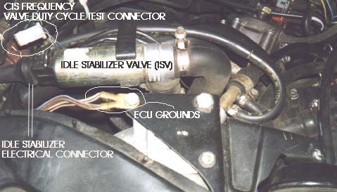
The CIS Frequency Valve (Mixture Control), Waste Gate Frequency Valve,
Cold Start Valve and the Carbon Canister Valve(s) can be tested using
the Output Test.
Engine Control Unit (ECU) Vacuum/Boost line
In order for the ECU to work correctly, it must receive an accurate pressure signal (vacuum or boost) from the intake manifold. There is a plastic line with rubber hoses on each end connected from the ECU to the intake manifold.
The vacuum/boost line (Green plastic line and rubber hose) from the intake manifold to the ECU should be checked for leaks if you are getting too much boost or a fault code 2221, 2222 or 2224. You can connect a hand vacuum pump to the line after removing it from the back of the intake manifold and see if it holds vacuum. If you have access to compressed air and have an accurate pressure regulator, you can apply 10-15psi to the vacuum/boost line and listen for any leaks. If you turn on the ignition, (Don't start the engine) you can read the boost pressure off the digital instrument panel boost pressure display, and see if it corresponds to the actual pressure applied to the ECU line from the air pressure regulator.
BE CAREFUL WHEN APPLYING PRESSURE TO THIS LINE, DO NOT EXCEED 15PSI OF PRESSURE OR THE INTERNAL ECU PRESSURE SENSOR COULD BE DAMAGED
There is a plastic moisture trap installed in the vacuum/boost line about a foot before where the line connects to the ECU. On the 10V Turbo engines, you have to pull back the carpet and padding in the passenger foot well to inspect this moisture trap. The 20V Motronic ECU has the moisture trap located next to the ECU underneath the kick panel cover.
INTAKE MANIFOLD ENGINE GROUND WIRE
The ground wire terminal connectors underneath the bolt on top of the intake manifold should be checked for a poor connection. A loose or poor ground connection at the engine can cause some strange running and hard starting problems. In some cases Loctite thread locking compound on the threads may prevent a good ground connection. Remove the 10mm bolt and inspect the contact area for excessive paint, clean the threads and re-install. Here is a close up shot of the "two" terminal lug connections at the rear area on the intake manifold from a 1989 200TQ.
NOTE: The earlier 1986-88 5000TQ vehicles may have only "one" terminal lug with ground wires at this location.
There is also a ground cable from the rear end of the valve cover, to the ignition coil mounting bracket that should be checked. The main Battery ground underneath the back seat should be checked for a clean connection to the body as this cable is susceptible to corrosion from the battery acid fumes. Other important grounds that should be checked, include: the main engine ground cable under the driver-side engine mount bracket, and the other harness ground wire cables nearby this main engine ground that attach to the body.
ECU has CUT WIRES at the Connector?
Don't be alarmed if you notice some cut wires on the Mac10 and Mac11 ECU wiring harness at the ECU Connector. The wire at Pin 6 on the ECU connector is normally cut for vehicles with manual transmissions (Quattro or 5 Speed FWD). The wire at Pin 34 will also be cut on NON-California Vehicles for emission changes.
Water/Corrosion at ECU connector?
I ran across a weird problem the other day, a customers 1990 200TQ Wagen was stalling intermittently at stop lights, and running poorly intermittently, it finally died as he drove to his home and would not restart. There was no ignition spark, and when I tried to pull out the ECU fault codes, the ECU did not respond either to the VAG1552 scan tool or to the procedure for using the LED to blink out the fault codes..
I pulled the kick panel off that covers the ECU and noticed that the plastic bag covering the ECU connector was torn and water was all over the ECU connector. I pulled up the ECU connector and the terminal pins were soaked in water and had some blue corrosion goo. The connector harness terminals were not severely corroded, and cleaned up nicely. The ECU was opened up and dried out, but the car still had no spark after re-installing the dried out ECU. I had to replace the ECU with a used unit, as some internal circuitry was apparently damaged by the corrosion/water at the connector when the car was running. I repaired the torn plastic bag over the connector to ensure this won't happen again. Apparently the owner had left the passenger side window open during a rainstorm and some water made it down along the interior.
The Bentley manual actually listed some fault codes for the knock sensor that can be caused by moisture inside the ECU, so keep this in mind when trouble-shooting.
Ignition Distributors used in the 10V Turbo Engines (KH and MC Designation)
There were two different ignition distributors used MC engines. In the KH and early MC engines, the Bosch 0 237 028 007 with Audi 035 905 206AF part number was used which has a rotor shaft of 0.560 inch diameter (~14.2mm). The later MC engines shows the replacement distributor as a Bosch 0 237 522 011 (Audi 035 905 206AF) which has a rotor shaft with 0.394inches (10mm) diameter. On these 10V turbo engines, I have also seen a Bosch 0 237 522 005 distributor originally used which also had the Audi part number 035 905 206AF . Any of these distributors can be used in the MC 10V engines, just keep in mind that you need to be aware of which rotor you need when replacement time comes around.
Loud Clicking Solenoid Valve under the hood on Audi 200
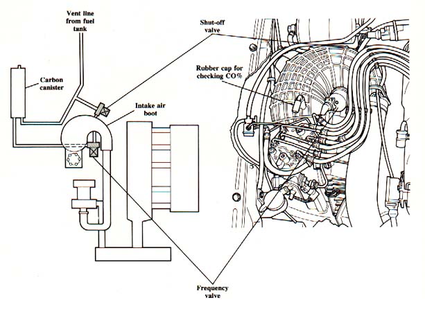
That loud clicking valve that is located on the rubber intake boot on the 1989-90 200TQ and on the 1989-91 200T with the dual knock sensor MC engine (10V) is a new valve for the 1989 Model year. It is the carbon canister frequency valve (aka solenoid) which regulates fuel vapors into the engine while it is running. It will come into play about a minute after the engine is started.
There is another solenoid type valve behind/below the intake air boot that regulates fuel vapors from the fuel tank that is normally opened above 1400 RPM to allow fumes to enter the intake system.
Here is a diagram showing the frequency valve location and the location of the shut off valve.
During normal operation at idle, the solenoid is turned on and off, and it does make a fair amount of noise, and often is mistaken for a noisy hydraulic lifter.
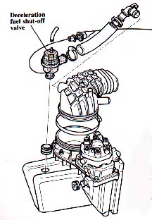
Stalling? Sticky Deceleration Valve? (Manual Transmission)
If your car stalls when coming to a stop and you have a manual transmission, one possibility is the deceleration valve is sticking open which would create a huge vacuum leak. Normally the idle stabilizer control unit turns this valve (solenoid) on and intake vacuum opens it, when you let off the gas and the RPM's are above 1200 RPM .
When the Decel valve opens it basically creates a big vacuum leak between the rubber boot above the CIS air flow plate and below the plate in the lower air filter housing. This big leak allows the CIS air flow plate to drop down and effectively shut off the fuel during deceleration so as to keep emissions low.
These valves have been known to stick open and then not shut when the RPM drops below 1200 which causes the big vacuum leak and the stalling. The valve is buried behind the r/side fender behind the CIS assembly. You may need to pull the plastic fender liner out to get to it.
The small vacuum hose from the decel valve should be connected to the back of the intake manifold via the small metal pipe fitting. There may be a plastic tee fitting nearby which also connects this manifold hose to the lower fitting on the waste gate solenoid. Basically this hose has intake manifold vacuum/pressure applied to it.
There is a larger rubber hose ~3/4 inch diameter that you can see from above that is routed from the big CIS intake boot down behind the fender to the decel valve (just in front of the fuel filter), if you are able to pinch off this hose, you can see if the car no longer stalls during deceleration.
You could also have a problem with the idle stabilizer control unit, or the temp sensor for this unit, the idle stabilizer control unit could be defective and keeping the decel valve on even after the RPM drops below 1200 RPM. Go to the CIS Fuel System page, Idle Mixture sectionfor more details on this idle stabilizer system.
Here is a picture of the valve and the location on the CIS air filter box.
Go to ECU System Technical Tips
References: [3] Audi of America service training publications: "1986 Model Change Information-publication "1989 Model Change Information-publication [6] Audi 5000 1984-88 Repair Manual, Robert Bentley, Inc. All rights reserved. Copyright © SJM Autotechnik™ , all rights reserved
Return to Troubleshooting Tips page. Return to SJM Autotechnik™ main page.
|
| About Us Privacy Policy Terms of Use Links Customer Service Safety Information Home |