The ABC's of Running High BoostLow or High boost ProblemsPoor Engine Running Trouble-Shooting 1986-88 5000T/Q, 1989-90 200TQ, 1989-91 200T With 10V Five Cylinder MC Engine For the 1991 200TQ 20V and 1992-96 S4/S6, please go to this20V Page for details. Important Safety Information Introduction It should be your responsibility (or your mechanics) to check out and verify all the ECU and Fuel Injection system components mounted on your engine are working correctly BEFORE you do any type of modification that will raise the boost on your vehicle. Raising the boost on a high mileage car isn't a great idea UNTIL you get the stock system working correctly as it was originally designed when it left the factory. Usually what people do, is they decide to do a modification that will raise the boost on a car with 75,000 to 100,000 miles on it. The car may have all the original engine vacuum/breather hoses and fuel injection components etc. THEN they wonder why the car is not running well after raising the boost....and they wonder why the modified ECU or add on boost control device is not making any more boost than it did when stock. Take a good look under your hood. When you use a modified ECU and a stock Waste Gate spring, the ECU can only raise the boost if the stock ECU/fuel system components on the engine are functioning correctly. If you install a stiffer Waste Gate spring or use a valve connected to boost pressure to add pressure on top of the Waste Gate Diaphragm, you may be unaware if the engine ECU/Fuel system components are not working correctly, because the boost may be raised regardless of the condition of the stock system components. Most of these high mileage cars have systems that are not working correctly with the STOCK level of boost, much less with 2 TIMES the stock boost level. The sad part is, many people are driving cars with inoperative components, leaky breather hoses and injector seals (MC Engine), defective throttle switches, mis-adjusted fuel injection mixture and don't know it because the car SEEMS to run "ok". Often times these same people comment on how lousy the CIS fuel injection system is, how it has driveability problems etc. The CIS system works very well when it is setup correctly and all the stock components are functioning as designed. Whenever I purchase a high mileage (70k>) Turbocharged Audi, I recommend you do the following:
After performing all the work mentioned above, I know these items are working correctly and then I don't need to "guess" if they are ok if the car starts running poorly. Don't get lazy and "assume" these components are ok, just bite the bullet and inspect or replace them as necessary. Enough ranting from me on this subject.... NOTE: Increasing the boost on your vehicle may change the emissions output which may not be legal in your area. Stock Boost Levels-How does the ECU control Boost? The 1986-88 5000T/Q and the early 1989 200T/Q with the single knock sensor MC designated engine with 7:8 to 1 compression, were designed to run 1.42 bar boost (absolute) as maintained by the MAC11 Engine Control Unit (ECU). This 1.42 bar absolute pressure, corresponds to ~6.1 psi gauge pressure. The later 1989-90 200T/Q, and 1991 200T with the dual knock sensor MC designated engine with 8:4 to 1 compression, had slightly lower boost levels, set to 1.39 bar (absolute) by the MAC14 ECU. This 1.39 bar absolute pressure, corresponds to about 5.6psi gauge pressure. The boost is set to slightly different levels, depending on the engine RPM and air temp by the ECU. Normally without ECU assisted boost control, when the boost control system is NOT working correctly, the boost produced will only be around 1.2 to 1.3 bar, as provided only by the waste gate being held closed by the stock waste gate spring tension. The ECU is designed to cycle the waste gate solenoid with a varying duty cycle, to allow the waste gate solenoid to add manifold boost pressure on top of the waste gate diaphragm, to assist and hold the waste gate closed and help the waste gate spring pressure. The MAC11 uses these boost values: RPM 1000 2000 3000 4000 5000 5500 6000 6375 Boost map value 1.04 1.35 1.4 1.4 1.4 1.42 1.4 1.4 Here are the following boost values used in the MAC14: RPM 2000 2975 4000 5000 5325 5575 6000 6375 Boost map value 1.36 1.38 1.37 1.375 1.39 1.39 1.38 1.37 Keep in mind that the stock boost pressure display in the instrument cluster, is often too slow to respond to rapid boost changes which can make it difficult to read actual boost levels. The resolution (0.1 bar) of the digital readout can also make it difficult to know if you have 1.3 bar or actually 1.39 bar. If your boost level seems low, you may want to connect a separate analog type boost gauge to verify the actual boost level produced. The Bentley manual has details on checking the boost with a separate gauge. Low Boost Problem Checklist Here is a checklist you can go through when you have low boost problems.
Overboost Problems (BOOST TOO HIGH)
Self Diagnostic System-Fault Codes The self-diagnostic system test should be run before you have your stock ECU modified, to make sure that there are no faults in any of the components (knock sensors, coolant/air temp sensors, throttle switch etc.) that the ECU relies on for correct engine operation. You need to do a 3rd gear full throttle run to exercise this diagnostic system correctly. The car should not be shut off after doing this full throttle run on the 86-88 1/2 5000TQ and early 1989 200TQ's (MAC10/11 ECU) as the fault memory will be erased. The later 1989 Model 200 Turbo and 200 Turbo Quattro and 1990-91 200T/Q's with dual knock sensors that use the MAC14 ECU (10V Turbo), have a non volatile memory for the fault codes that can be read later even if the engine has been turned off after the test drive. The ECU system OUTPUT tests should also be done on the stock ECU before doing any modifications to verify that the CIS Frequency valve, the Wastegate Solenoid, the Cold Start valve, and the Carbon Canister valve, are working correctly. In some cases the ECU internal drive transistors for these solenoids can be defective and will prevent correct operation of the engines fuel and boost control systems. If there is a problem with any of the solenoids or the internal operation of the ECU, this needs to be known BEFORE you send in a ECU for modification. Go to the "10V Turbo ECU Fault Codes" page for details on running the output tests. Check ECU Connector Terminals for Corrosion If you are having some running or boost problems, you may want to inspect the ECU Connector terminals for any subtle corrosion on the tin plated terminals and use some electronic contact/terminal cleaner on them, along with some contact enhancer. The plastic bag cover over the connector should be installed correctly with no tears in the plastic to avoid any water or moisture from dripping down onto the connector and wiring and keep water out of the ECU. Sometimes just removing the large ECU Connector will cure some problems as the action of removing and installing the large connector wipes clean the connector terminals. Check basic engine timing, flywheel, camshaft and distributor rotor position You should check the basic engine timing, the flywheel should be placed at TDC with the O mark lined up in the transmission window, the camshaft gear dot or line mark on the back side of the gear should be set to line up with the gasket edge of the valve cover, and the distributor rotor should be set to the #1 cylinder line on the rim of the distributor. The Bentley manual has the details on setting these correctly, normally this is done when the timing belt or distributor is replaced. Additional details can be found on the engine page. NOTE: In some cases the front lower crank timing gear will rotate back and forth on the crankshaft snout if the gear keyway has sheared off, and this gear slippage on the crankshaft will allow the camshaft timing to change back and forth which may look like the basic flywheel/cam/distributor timing is off. The timing gear keyway shears off because the previous timing belt repair job was not done correctly and the front crank pulley bolt was not tightened enough using the correct special tools. You may want to rotate the front crank pulley back and forth, while you watch for the same movement response at the camshaft gear. If there is a large delay in movement at the camshaft gear when you rotate the crank pulley, you may have a problem at the lower crank timing gear behind the crank pulley. Throttle Cable Adjustment It is a good idea to check the throttle cable adjustment to ensure the throttle is being opened all the way and the Wide Open Throttle (WOT) contacts inside the throttle switch are being closed when the gas pedal is pushed all the way down to the floor. With the engine off, have a friend push down on the gas pedal inside the car, while you check the throttle lever under the hood. The throttle lever should be pulled all the way back with the gas pedal pushed down all the way to the floor. If the throttle is not being opened all the way, remove the "C" shaped circlip from one of the slots around the throttle cable shaft, and then slowly pull the rear portion of the throttle cable until the throttle is opened all the way. Don't over do this, as you don't want to pull it too far back, and make the throttle cable too short, which would put it under excessive tension at WOT and cause it to break eventually. Throttle Linkage, Cruise Control Check Some owners have mentioned that they have had trouble with the Cruise Control linkage coming apart which caused the throttle to stick open at the most inopportune time. Apparently the cruise control linkage bushing falls apart, which allows the linkage to fall down and jam the throttle open. Others have reported trouble with the throttle linkage dash pot coming loose and with the same throttle jamming results. Check the throttle return linkage and dash pot, and replace any cruise control linkage bushings or rods that look questionable. Ignition Wires? Distributor Cap shorting out? The Audi OE ignition wires have a stranded copper wire and use resistive spark plug connectors that each have ~5k ohms. The other end of the ignition wire that plugs into the distributor cap has a resistive connector end with approximately 1k ohms. In many cases the spark plug ends can have too much resistance and will cause a misfire under load. If you have a misfire under load, in some cases the cylinder #5 spark plug connector end or the wire will short to the breather hose metal tube if it is too close to the wire. You may need to position the breather pipe away from wire to avoid a misfire. I have also found that the distributor cap outer black shield can short internally and cause strange running conditions and misfires. Are you using the correct Spark
Plugs? The Tri-electrode plugs are gapped at the factory, the specified gap
is 0.028-0.035 inch, (0.7-0.9mm) It is also a good idea to check the torque of the spark plugs, as they
can come loose. The spec for the new W7DTC Tri-Electrode spark plugs
is 14 lb-ft as used in the 10V engines. Throttle Switch Defective? A defective throttle switch (full throttle switch - MC Engines) will prevent the correct operation of the Waste Gate (WG) solenoid system that the ECU uses to adjust the turbo boost. If you are running a stock Waste Gate Spring with a modified ECU that has a re mapped boost map with higher values, this full throttle switch MUST be working to allow the ECU to use the new higher boost map and make more boost by applying pressure to the top of the Waste Gate. If your car has high mileage and the original throttle switch, I can just about guarantee your throttle switch is defective or intermittent as they have internal solder connections that crack over time. I recommend replacing this switch on these high mileage cars. Also make sure you run the tests on the Multi-function Temp Sensor, as this will also test the throttle switch wiring from the switch to the ECU. Go to the ECU System Component section for specific details on checking this throttle switch. Note: Using a stiffer Waste Gate spring can be a good idea on the MC engines as it will improve the rate at which boost is produced, but...... it can mask problems with the ECU system components (Throttle switch/throttle potentiometer etc.) as the boost will be mostly controlled by the stiffer Waste Gate Spring. Multi-Function Temp. Sensor-Defective? One additional sensor to check when having low boost problems, is the Multi-function Temperature sensor. This sensor is mounted underneath the coolant outlet on the cylinder head and provides a resistive signal for the coolant temperature gauge, provides a Overheat warning signal to the Auto-Check system, and lastly provides an Overheat signal to the Engine Control Unit (ECU) which can limit boost if the coolant temperature exceeds 247F, 119C. This Multi-function temp sensor has 4 terminals and uses a 4 terminal connector which is normally is covered with a protective rubber boot. The newer style replacement Sensors will have only 3 terminals as they simplified the internal design of this sensor and eliminated the +12V supply to this sensor. The Engine Cooling System section has details on this sensor operation Additional information in the ECU System Component page section to ensure this sensor is not causing the low boost problem. Engine Control Unit (ECU) Coolant Temperature Sensor Details on this single wire sensor HERE Air Temperature Sensor The air temp sensor that the ECU uses to monitor the intake air temperature often can have poor or broken wiring connections at the sensor. Often times the connections will be intermittent on these cars and the boost will be regulated to a lower setting by the ECU. It is very important to visually check the wiring connections at the sensor, as well as using an ohm meter at the ECU connector terminals to verify the wiring from the sensor to the ECU is intact. This sensor is located on the intercooler exit. The wire terminals are normally soldered or spot welded to the air temp sensor. Factory replacement air temp sensors use a separate connector with gold plated terminals. Go to the ECU System Component section for specific details on checking this sensor. Engine Control Unit (ECU)
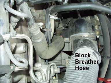
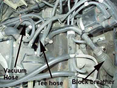
Vacuum/Boost line Vacuum Leaks-Breather Hoses!
The two small idle stabilizer hoses should be removed and checked
also as they can get blown off from the pressure. VALVE COVER GASKET Vacuum/Boost Leaks at Injector Air Shroud Hose? 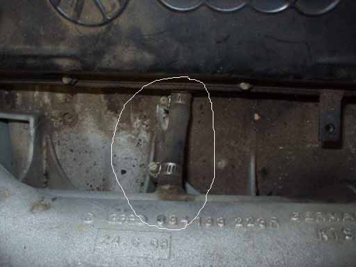 These 10V Five Cylinder Turbo Engines use Air Shrouded Injectors which require a fresh air supply hose from the intake manifold to the Cylinder head. This photo shows the hose with the injectors removed from the engine. 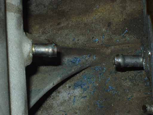
With the hose removed you can see the fittings. The MC-2 Engine with Dual Knock Sensors have an Orifice located inside the middle of this hose, so make sure you remove the orifice and insert it into the new section of hose when replacing. The small Orifice hole goes toward the Intake manifold. 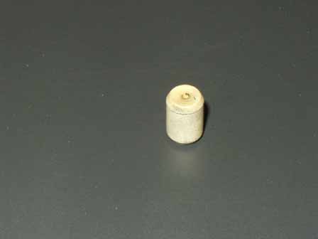
MC-2 Air Shroud Hose Orifice Boost Leaks-Turbo and Intercooler hoses, Turbo Checks, Intercooler Leaks The accordion-style hose that connects the intercooler exit to the intake manifold normally rots (from oil) over time and will split at the bottom between the ribs while under high boost. Remove and check it. If your MC engine car has over 75,000 miles on it and this hose has never been replaced, save yourself some grief and BUY A NEW HOSE NOW!. On the MC engines, these old stock accordion hoses ALWAYS seem to fail after you raise the boost, ALWAYS! Do ya catch my drift? Some companies offer heavy duty silicone hoses for this application, but fitting them can be a problem. I have never tried them out, so I can't recommend them at this time. After replacing this accordion hose with a stock replacement part, I have run the engine with 2.25 bar boost for several years with no failure of this stock hose. The curved turbo intake hose elbow that connects to the metal intake pipe should be removed and checked for cracks, be careful of the small hoses attached to this elbow. While you have the intake hose off the turbo, you may also want to check the cold side turbo shaft for excessive play. The earlier K26 watercooled turbo Audis spec the max end play to be 0.0043 inches, and the cold side compressor side play to be no more than 0.025 inches. The water cooled K24 turbo Audis spec the max end play to be 0.0035 inches, and the cold side compressor side play to be no more than 0.025 inches. Normally you need a dial indicator to accurately measure this. You should also look for any metal shrapnel caused by worn turbo bearings which may have allowed the turbo compressor blade to rub against the turbo housing. The turbo exit hose (turbo pressure) going to the intercooler should be removed and checked as well. The later 200TQ's with the MC dual knock sensor engine and smaller K24 turbo have a plastic pipe connected between the turbo exit hose and the intercooler and a short rubber bellow hose. This plastic pipe has some "insulation foam" inside and it should be removed and checked. This foam is either for sound deadening or is used to collect oil. Sometimes this insulation foam will come loose and get blown into the intercooler. (Major restriction!) The short section of rubber bellows can also split and leak. Often times, the hose clamps for these pressure hoses are just loose and they will leak under high boost. The intercooler end cap seals can leak under high boost and you should install some large straps or one or two large hose clamps around the intercooler to hold it together under high boost. Many hydraulic supply houses carry the screw type hose clamps that are 4 ft long which fit around the intercooler nicely. Because there normally is an oil mist flowing through the intercooler, any leaks around the intercooler seals will show up as oil seepage out of the intercooler end caps. In some cases you can carefully re-crimp the aluminum tabs that hold the plastic end tanks on to tighten up the end cap seal. The internal intercooler rubber seal on the inlet side that seals the internal upper and lower sections of the intercooler should be checked when you remove the hoses from the intercooler. You should look inside the intercooler and make sure this seal has not blown out which would allow the air entering the lower chamber of the intercooler to bypass the intercooler and go straight up into the exit pipe and into the intake manifold without any cooling effect. Knock Sensor Intermittent? Hesitation? Low Power? Check Engine light On? If your 1986-88 5000TQ or 1989-91 200T/Q is running poorly or the "Check Engine" light has come on, it is possible that the ECU is detecting a fault in the knock sensor system caused by a loose, defective or intermittent knock sensor. There may also be a problem with the knock sensor wiring or connectors. The replacement knock sensors have gold plated terminals and the wiring harness connector terminal pins should be replaced with these gold plated versions as well. For additional details on the knock sensors, please go to MC Engine Knock Sensor(s) for details on the 1986-91 5000/200 Turbo or 1986-990 5000/200 Turbo Quattro. The MAC11 ECU used in the 1986-88 5000 Turbo and Turbo Quattro and in the early 1989 200 Turbo and Turbo Quattro (Before VIN # KN038262) does not remember fault codes after you turn off the ignition which may explain why the car may work ok after a re-start. When the car begins running poorly, you may want to leave it running and then check for any fault codes. Check the ECU fault code section for details on checking for any stored codes. The later 1989-91 200TQ with the dual knock sensor equipped MC engine (MAC14 ECU) uses the "Green" color coded knock sensor for cylinders #1 and #2, and the "Brown" color coded Knock sensor for Cylinders #3, #4, and #. These dual knock sensor MC engines can have the same knock sensor problems as above, but they use an ECU which has a static RAM that is used to store fault codes even after the ignition is shut off. Some of the 1989-91 200T/Q's have the "Check Engine" light bulb removed from the dash, so if the car is having a problem with one or both of the knock sensors, you may not know it. The "Check Engine" light should come on with the ignition key turned on to the first position. NOTE: The Knock regulation system only operates after the engine coolant temp is above 70 C (158F) and when the manifold pressure is above 0.7 bar absolute and the idle switch is open. With a stock Waste Gate spring, the ECU will only raise the boost after the engine warms up as well. This is one reason why you want to take it easy on the engine and keep the boost down until it gets warmed up. Fuel Injectors The fuel injector brass and plastic inserts that are screwed into the cylinder head should be replaced along with the 3 rubber O-rings sealing the fuel injectors and inserts. You want to ensure there are not any vacuum or boost leaks from these inserts or from the injector seals. Vacuum leaks at this area will often cause hard starting and an uneven idle speed. The green Viton injector O-rings should always be used instead of the older style black rubber O-rings. The older Black O-rings can't take the heat over time and get hard quickly and lose the ability to seal the injector to the insert. The injectors can be blown out of the cylinder head if they have tired/hard O-rings. Leaky or seeping fuel injectors can increase the hot/cold starting times. Dirty/clogged injectors with poor spray patterns can reduce low end torque and cause uneven performance when cold. More details can be found on this page CIS Fuel Injection System Intake valve carbon deposits can also cause cold running problems as the carbon acts like a sponge, soaking up the fuel at first. You should look at the back of the intake valves when you have the injectors out of the cylinder head when you replace the injector inserts. With severe carbon buildup some repair shops can use a walnut shell blasting device to clean off the carbon buildup. Lighter buildup can be removed with the use of a fuel additive or a fuel with Techron. Vacuum/pressure leaks anywhere in all of the above mentioned areas may cause lean/rich running and hard starting. You may also want to have a mechanic check that the CIS fuel injection system pressures are correct (system pressure and warm up regulator control pressure). After verifying there are no vacuum/pressure leaks, and the fuel system pressures are correct, the basic idle mixture CO% should be checked and adjusted if necessary. Intake Boot-Decel Valve The main fuel distributor rubber boot should be visually checked for cracks with a flashlight and a mirror especially around the edge where the large clamp holds the boot to the fuel distributor opening. The decel valve located on the CIS air box assembly (behind the fender) and large rubber hose going to the fuel distributor rubber boot could also be the source of a vacuum leak. There was a service bulletin issued for the 86-90 5000TQ/200TQs that mentions a stalling problem during deceleration that is caused by a decel valve that sticks open causing a huge vacuum leak. Go to ECU System for more details on the Decel valve operation. There are also charcoal canister purge valve(s) (late 89 has two) that should be checked for correct operation using the ECU Output test. Idle Stabilizer Valve (ISV) and Control Unit The idle stabilizer valve (ISV) can also stick from oil/crude built up inside and this can cause strange high idle conditions. Cleaning the ISV with carb cleaner may help. The hoses on the ISV valve to the intake manifold can blow off under boost, or can be cracked and cause a loss in boost pressure. There is a separate Idle Speed Stabilizer Control Unit (Double wide Relay) located under the driver side dash on the relay panel. This control unit uses a single wire coolant temp sensor mounted on top of the coolant outlet on the cylinder head and is grounded through the threads on the sensor. In some cases corrosion between the threads on this sensor will cause strange idle behavior due to the resistance change. See Idle Speed and Idle Mixture procedure for additional information on idle problems. Link to Fuel Injection, Technical Tips O2 Sensor Replacement The O2 sensor should be replaced if it has over 60k miles on it, or if you are having lean surging during light throttle conditions, poor cold running problems during engine warm up, or emissions related failures. Older O2 sensors can get contaminated and will respond too slowly to correctly adjust the mixture. See the 10V O2 Sensor section for details. Idle Speed/Mixture Adjustment/Check: The Idle Speed adjustment should be checked before adjusting the idle mixture. The CO% idle mixture adjustment is also referred to as the frequency valve duty cycle adjustment. The Engine Control Unit (ECU) controls the operation of the frequency valve via a changing duty cycle signal. In response to the O2 sensor voltage signal the ECU receives, the ECU changes the duty cycle controlling the frequency valve and this adjusts the fuel mixture slightly rich or lean as needed. The frequency valve changes the lower chamber pressure inside the fuel distributor which alters the amount of fuel sent out to each injector. Use the following Link to see the CIS Idle Speed and Idle Mixture Adjustment procedure. Link to Fuel Injection section, Technical Tips Waste Gate Controls The small hoses connected to the Waste Gate control solenoid and to the upper cap on the Waste Gate (WG) should be checked for cracks. The large hose from the intake manifold to the lower chamber in the waste gate should also be checked for cracks/leaks or restrictions, as any leaks or restrictions could prevent the waste gate from opening to control the boost level. The Waste Gate Solenoid inlets are connected to the intake manifold and to the turbo intake boot. This solenoid mixes the pressurized air from the intake manifold and the air from the turbo intake (slight vacuum) and applies this pressurized air to the top of the WG diaphragm to assist holding the WG closed. The pressurized air applied to the top of the WG diaphragm assists holding the WG closed along with the WG spring tension. Go to the wastegate section for details on checking the operation of the waste gate control system. Exhaust System Issues You should have the exhaust back pressure checked by a muffler shop if you have low boost conditions and suspect a plugged catalytic converter or muffler/exhaust system. They can use the pre-catalytic converter sniffer pipe bolted to the intake manifold to do this, or they can drill a small hole in the exhaust pipe to insert the pressure gauge pipe. A low pressure (0-10 psi) fuel pump pressure gauge can be used for this. Typically with the car idling in neutral, as you slowly rev the engine to 4000 RPM and hold it at 4000 RPM, the exhaust back pressure should not increase above 1-2 psi. If you run a long hose from the sniffer pipe to a gauge inside the car, an assistant can check the exhaust back pressure while you drive the car. Test Example: When the car is driven and under load in 3rd gear at WOT and near redline, it is not unusual to see over 5psi of back pressure when running 1.8 bar of boost pressure. The older catalytic converters can create some of this back pressure and may need to be replaced as the car gets over 75K miles. Running higher boost can affect the exhaust manifold/system. Cracked exhaust manifolds and or broken exhaust studs can result even running stock levels of boost in these vehicles. As mentioned, the catalytic converter and muffler system can get plugged or restricted over the life of a car which may cause poor running with low power. Ignition misfires are the biggest cause of catalytic converter meltdown due to the extreme temperatures created when raw fuel (hydrocarbons) (HC) and the unused oxygen passes out of the misfiring cylinder unburned and then goes into the catalytic converter and are oxidized. Rich mixtures won't necessarily hurt the catalytic converter, as long as the rich mixture is burned well with low hydrocarbon exhaust levels. In some cases when running a car at high speeds with a very rich mixture at Wide Open Throttle (WOT) that is then followed by a rapid stop and idling, the catalytic converter may get very hot. If you ever need a reminder to let your engine run after a high boost run, just open up your hood at night and see the red hot exhaust manifold and turbo! Even with the water cooled turbo you should let the car idle for several minutes. It may take 10-15 minutes of normal low boost driving before the exhaust manifold/turbo cool down. It is a good idea to avoid high boost initially after starting a cold engine until the oil temp gets up to 60C (this is recommended in the factory operators manual). Cooling System checks The engines cooling system needs to be working correctly before you decide to up the boost on your car. The Engine Control Unit uses a coolant temp sensor that should be tested if cold or hot start problems, or other warm running problems are occurring. Go to the ECU System Components page for details on checking this coolant temp sensor. All the coolant hoses should be checked/replaced as needed and the cooling system should be flushed out and refilled with the correct mix of coolant. The thermostat should be replaced with the originally specified 87 degree Celsius version if it is several years old. Often times a malfunctioning thermostat will cause low boost and other engine running problems, if the engine is running too cool or too hot. The after run cooling fan and turbo pump should be checked for correct operation. Go to the Cooling system page in the Trouble-Shooting section for additional details. Drivetrain Issues Driving with more boost/horsepower places more stress on the transmission, clutch, suspension system and tires. The Audi I5 turbo engines are very robust motors but running Higher Boost levels obviously places some additional stress on the internal engine components. You may want to do a compression test to locate any weak cylinders before raising the boost. People running cars with automatic transmissions may want to limit how much your boost level increases as these transmissions are not very robust. FWD cars may become dangerous to drive under high boost levels as they tend to torque steer and this may result in the loss of control and an accident. The two hydraulic engine mounts and the rear transmission mounts should be checked and replaced as needed, the exhaust side (passenger side) engine mount is subjected to a lot of heat (check that the hose is installed correctly that provides fresh air to this mount). A defective hydraulic engine mount on this side tends to place more stress on the exhaust manifold/system. Of course the tires, CV joints, wheel bearings, shocks, sub frame bushings and other suspension bushings/parts subject to wear and tear should be replaced where necessary. Having more power will make the car a handful to drive if you have a worn out suspension as you will discover in short order. Better to fix it now than to crash and burn it later. Stock Digital Boost Gauge, Aftermarket Boost Gauge, Pressure Conversion Info. The stock digital boost gauge located in the instrument cluster displays the intake manifold "absolute" boost pressure, from ~0.0 bar to 2.0 bar. For more details, go to the Stock Boost Gauge page MC Turbo Engine, early 1989 vs late 1989 200 TQ There were some mid-89 model year changes made to the "MC" designated engine for the 200TQ cars. Keep in mind that the actual "production" dates (shown on the driver's side pillar) for the 89 model year cars start around 6/88. I recently bought an "89" 200TQ that has the later MC engine with dual knock sensors, smaller turbo, different computer (MAC 14), different camshaft etc. that has a production date of 12/88. The change to the dual knock sensor engine with above changes occurred in 11/88 at VIN # 44KN038262. One way to tell the earlier and later engines apart is to look on the firewall where the connectors are mounted for the knock sensor(s), and the two crank/flywheel sensors. The later model MC engine will have 4 connectors versus the 3 connectors on the earlier MC with the single knock sensor connection. (Note: This applies to the US version MC with O2 sensor) You can also look for the second knock sensor mounted toward the rear of the engine block. Single Pass Intercooler from US 1991 200TQ 20V, and Euro 10V engines For details on the Single Pass Intercoolers, go to Single Pass Intercooler page for more details. Copyright © SJM Autotechnik™ , all rights reserved Return to Trouble-Shooting Tips page. Return to SJM Autotechnik™ main page. |
| About Us Privacy Policy Terms of Use Links Customer Service Safety Information Home |