Engine, Technical Tips1986-91 5000/200TQ 1992-95 Audi S4/S6
Engine Oil Grade Temperature Chart for 1989-91 Audi 200TQ including 20V 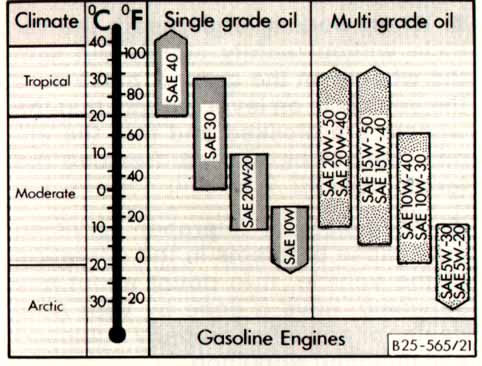
1995 Audi S6 with 20V Five Cylinder Turbo Engine Oil Grade Temperature Chart Group A Oils are "Energy Conserving Oil" Group B Oils are "Multi-grade Oil" 1984-85 5000T KH Turbo Engine, MC Turbo Engine, 1986-88 5000T/Q
The water cooled turbo was added in the 1985 Model year, so you will find that some of the 1985 KH designated 2.1 liter 5000 Turbo engines with a water cooled Turbo installed, and the after-run turbo cooling pump. It is a good idea to double check the engine block Serial number and 2 letter designation stamping on the top side of the drivers side engine block just below the cylinder head. You should see the letters KH stamped in front of the engine serial number.
These '84-85 KH engines have a knock sensor like the later MC engines but use the Hitachi MAC-07 ECU instead of the MAC10 or MAC11 ECU. A few people have been fooled into buying these 2.1 liter KH engines for turbo conversions when they thought they were buying a MC 2.22 liter.
The MC engine (Single Knock Sensor version) is shown in the Audi parts fiche to be used from build dates of 8/85 to 4/88 in the 1986-88 model year 5000T/Q and from 5/88 to 10/88 in the early 1989 model year 200TQ vehicles. Early 1989 200T/Q vs Late 1989 200T/Q, 1989 Model Year Changes, Dual Knock Sensor Engine MC Engine Timing Belt Changes
There were some mid-89 model year changes made to the "MC" designated engine for the Audi 200 Turbo Quattro cars. Keep in mind that the actual "production" dates (shown on the driver's side pillar) for the 89 model year cars start from 5/88.
I recently bought an "89" 200TQ that has the later MC engine with dual knock sensors, smaller turbo, different computer (MAC 14), different camshaft etc. that has a production date of 12/88.
The change to the dual knock sensor engine with above changes occurred in 11/88 at VIN # 44 KN 038264 for the 200TQ.
The 1989 Audi 200 Turbo vehicles with Front Wheel Drive (FWD) apparently had this change to the later dual knock sensor MC engine approximately at VIN 44 KN 020000.
Here is a picture of the dual knock sensor location on these later
MC engines for identification purposes.
One way to tell the earlier and later engines apart is to look on the firewall where the connectors are mounted for the knock sensor(s), and the two crank/flywheel sensors. The later model MC engine will have 4 connectors versus the 3 connectors on the earlier MC with the single knock sensor connection. (Note: This applies to the US version MC with O2 sensor) You can also look for the second knock sensor mounted toward the rear of the engine block.
The factory training service book (89 Model year changes) indicates that the engine has more low end torque but the same HP output
TIMING BELT CHANGES The Timing belt was also changed on the these MC engines in 89. The newer timing belt has teeth that are rounded slightly and is referred to the "Super Torque" style belt.
According to the Audi parts fiche, this occurred in Model year 1989 at VIN 44KN004458 so check your VIN number and visually inspect the belt before ordering parts as these VIN changes don't always occur exactly for every vehicle that was produced. The water pump, crank and cam gears will be different as well.
I recommend you bring in your VIN number and inspect the parts on your car any time you need to purchase engine parts for these 1989 200 Turbo Quattro and 1989 Audi 200 Turbo vehicles.
I read in one magazine review that the 89 model year vehicles have around 1500 new parts. The newer style interior with Air bag etc. must account for a large portion of these 1500 parts. A technician I know that works at the local Audi dealer said the only change he could think of that occurred in the 90 200TQ was a different type of wood used for the dash, something that was apparently not on the endangered species list. One of the Audi service bulletins indicates that the wood trim finish process was improved in 11/89 to eliminate the cloudy/milky appearance that shows up in these cars. I would imagine there are other subtle changes as well on these 1990 model year 200TQ cars. (1/98) 1986-88 Audi 5000TQ, and Early 1989 200TQ versus the Late 1989 200TQ
The valve cover gasket for these 1989 Audi 200T/Q's is also slightly different and this changed in 1989 at VIN # KN043131.
The 1986-88 5000TQ and early 1989 200TQ use the -025D Valve Cover
Gasket set which is designed for mounting studs that have a shoulder
or step at the cylinder head gasket sealing surface. The photo below
shows the recessed copper washer in the rubber gasket that is designed
to fit over the shoulder on the mounting stud. Stepped or shouldered stud used with the -025D Valve cover Gasket Set
The later 89-90 200TQ after KN043131 use the -025C gasket set which is used with mounting studs that have NO step or shoulder. The photo below shows the Valve cover gasket which has the copper washer flush with the rubber gasket sealing surface.
Valve Cover Gasket Replacement on AAN S4/S6 Five Cylinder Turbo engine.
The valve cover gasket comes in 2 pieces, it has the center section
which seals the spark plug holes, and the outer section around the edge.
Replacing the valve cover gasket is fairly straight forward on these
AAN 5 cyl turbo engines. The heat shield on the side of the exhaust
has 2 nuts that need to come off, remove the coil packs, remove the
two breather hoses at the rear of the valve cover.
Camshaft valve timing specs for NF, MC-1, MC-2, and 3B engines [2]
Note: Valve timing designated at 1mm valve lift and zero clearance
NF designated 2.3 liter Naturally Aspirated Engine Intake opens before TDC 0 degrees Intake closes after BDC 41.1 degrees Exhaust opens before BDC 40.0 degrees Exhaust closes before TDC 1.1 degrees
KH designated 2.1 liter Turbocharged engine Intake opens before TDC 1.5 degrees Intake closes after BDC 38.7 Exhaust opens before BDC 41.5 Exhaust closes before TDC 1.3
MC-1 designated 2.22 liter turbocharged engine (single knock sensor version) Intake opens before TDC 0 degrees Intake closes after BDC 41.1 degrees Exhaust opens before BDC 40.0 degrees Exhaust closes before TDC 1.1 degrees
Measured lift from MC camshaft, Intake and Exhaust ~0.416 inches
MC-2 designated 2.22 liter turbocharged engine (dual knock sensor version) Intake opens before TDC 4 degrees Intake closes after BDC 41 degrees Exhaust opens before BDC 46 degrees Exhaust closes before TDC 5 degrees 3B and AAN designated 2.22 liter 20V Turbocharged engine Intake opens before TDC 3 degrees Intake closes after BDC 25 degrees Exhaust opens before BDC 42 degrees Exhaust closes before TDC 9 degrees Exhaust lift 8.6mm
RS2 Avant: ADU designated 2.22 liter 20V Turbocharged engine Intake open 13 degrees Intake Closes 35 degrees Exhaust open before 24 degrees Exhaust close 1 degree Exhaust lift 9.5mm
MB Engine used in UK ur-Quattro
The ur-Quattro in the UK received an engine that was similar to the MC style engine used in the US based 1986-88 5000TQ. It had the Mac12 ECU which is very similar in circuitry to the Mac11 with a single knock sensor and a similar Waste Gate solenoid, but it did not use the Oxygen sensor. The MB had higher compression at 8:6 to 1 and was designed to run on RON 98 fuel.
Special thanks to Phil Payne in the UK for these photos of his MB equipped ur-Quattro engine bay. Check out a great web site from the late great Phil Payne, Kerbside Motors
Timing Belt/Water Pump Replacement 10V Turbo MC Engine, 1991 200TQ 20V Turbo 3B Engine
I replaced the timing belt and water pump on my 1986 5000CS Turbo at 75K miles, on my 89 200TQ at ~80K miles. I purchased a 1988 5000TQ that had over 135K miles on the original timing belt.
Often times the age of the belt has more to do with the need to replace it more so than the actual mileage the engine has on it.
You can bend the valves in the cylinder head if you rotate the crankshaft and don't have the timing belt installed.
The crankshaft and camshaft ALWAYS need to rotate TOGETHER with the TIMING BELT INSTALLED to avoid bending the valves.
ALWAYS Set the engine at Top Dead Center (TDC) for Cylinder #1 BEFORE Taking the timing belt off.
The camshaft will make ONE complete rotation (360 Degrees) when the crankshaft is rotated around 2 complete rotations (720 Degrees)
These are considered "interference" engines, meaning that if the timing belt breaks, the valves in the cylinder head will contact the pistons and get BENT!
THIS REPAIR JOB SHOULD NOT BE TAKEN LIGHTLY!
The Bentley Repair manual should be consulted for this job, but here is the basic procedure.
Removing the bumper can make this job a little easier. The front bumper is held on with only two allen bolts underneath the front edge of the bumper. The alternator cooling hose should be removed along with loosening a few Phillips screws on the plastic air ducts by the A/C condenser to allow the bumper to slide forward and out. The turn signal bulb sockets will have to be twisted and removed as the bumper is pulled forward. The bumper wings on each side, just slide out of some retaining fixtures that are bolted to the fenders.
The front grill and intercooler can also be removed to allow better viewing of the timing belt.
The hardest part of this job, is loosening the crank pulley bolt and the cam pulley bolt.
I purchased the special tools Crank Damper pulley bolt extending wrench (2079) and the Damper Pulley locking tool (2084) from Zelenda in Forest Hills, NY Toll Free number is 888-892-8348. They sometimes carry used tools which can save some $$.
The cam pulley holding tool VW544 can also be purchased from a Mac Tools or Snap On Tool dealer. The Tensioner pulley puller 3034 is useful to remove this pulley.
The crank pulley bolt wrench 2079 is a socket welded onto a bar which allows a 3/4 inch drive breaker bar/Torque wrench to be attached. The bar also has a slight bend in it to get around various obstacles near the pulley.
The locking tool slips inside the crank pulley and engages the center ring and goes around the front engine mount bracket. You may need to push the rubber mount forward to allow getting the locking tool 2084 on with it sitting flat against the crank pulley.
I can't imagine doing it without the tools although many have used some interesting methods to get the pulley loose. I had a 3 foot breaker bar and it took all I had to break it loose. The bolt has some thread locking compound on the threads and the shaft which should be wire brushed off before re-installing.
Replacing the bolt certainly couldn't hurt while you are in there. The torque spec 'using' the 2079 crank pulley bolt wrench is 258 ft/lbs. While you have the damper pulley off, you should visually check out the internal rubber ring for excessive cracking. The damper pulley internal rubber ring condition and characteristics are important for reducing crankshaft torsional vibration.
BEFORE you loosen the crank pulley bolt, and replace the timing belt, you should become familiar with the timing marks on the flywheel, camshaft and the distributor.
First you should set the engine to be at Top Dead Center (TDC) for #1 cylinder. To set the engine to TDC for #1, remove the distributor cap and rotate the crankshaft bolt until the distributor rotor is pointing toward the front of the engine but exactly aligned with the line scribed on the edge of the distributor rim.
A black magic marker was used to highlight this line mark in the following
photos. 10V Turbocharged MC engine
20V Turbocharged 3B Engine You can also look at the distributor cap and locate cylinder #1 ignition wire post to make sure you have the distributor rotor pointed in the right direction (Towards the front of the engine). Rotate the crankshaft until the distributor rotor is close to being lined up..
As the distributor rotor approaches the line on the rim, you need
to locate the flywheel TDC mark by looking through the hole in the transmission
housing at the rear of the engine.
You may need to use some brake clean or solvent and a small wire brush
to clean the surface of the flywheel edge to see this TDC "O"
or Line mark.
You want to rotate the crankshaft until the 0 mark "center"
or the Line scribed in the flywheel is lined up with a flat shaped edge
on the transmission housing hole. This is done to get the engine at
TDC. 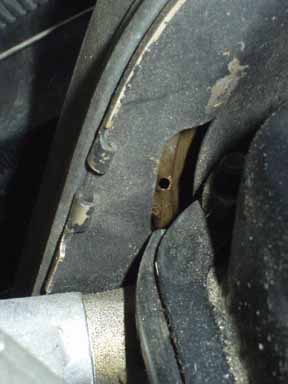 10V Turbocharged MC Engine Camshaft Gear Timing Mark 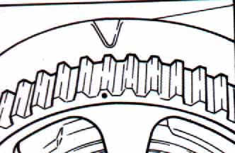 20V Turbocharged 3B Engine Camshaft gear timing mark IT IS IMPORTANT TO UNDERSTAND THAT THE CRANKSHAFT MAKES 2 REVOLUTIONS FOR EVERY 1 REVOLUTION OF THE CAMSHAFT.
IN OTHER WORDS, THE CRANKSHAFT TDC MARK ON THE FLYWHEEL COULD BE LINED UP IN THE TRANSMISSION HOUSING MARK, BUT THE CAMSHAFT TIMING COULD BE OFF 180 DEGREES.
YOU MUST VERIFY THE CAMSHAFT TIMING MARK OR THE DISTRIBUTOR TIMING MARK IS CORRECT TO VERIFY YOU HAVE ACCURATELY LOCATED TDC FOR CYL #1.
TIMING BELT REPLACEMENT:
After removing the power steering pump mounting bolts, the belt and moving the pump off to the side, remove the upper cam belt cover (two 6mm allen screws).
Loosen the alternator mounting and A/C compressor mounting and remove the alternator and A/C belt.
Loosen the camshaft gear bolt using the holding tool and a large 19mm wrench.
DO NOT REMOVE THE CAM GEAR BOLT YET!
NOTE: As mentioned, there is a special tool (of course) to hold the cam gear from turning during removal and installation of the retaining bolt which is usually VERY tight and a pain to loosen.
Avoid turning the cam with the timing belt removed or you may bend some valves.
The official VW/Audi Tool is VW544, but as mentioned, Mac Tools and Snap On Tools has a cam gear holding tool. You can make the special tool to hold the cam from turning if you are handy with a welding torch and have some steel stock.
Once you have loosened this cam gear bolt you can go ahead and "loosen" the crank pulley bolt, but do not remove the crank pulley bolt yet.
You need to rotate the engine away from the TDC CYL#1 setting you found previously to install the 2084 locking tool on the crank pulley.
Make sure the 2084 locking tool engaging the pulley correctly, you may need to move the front engine mount rubber forward to allow getting the 2084 around the engine mount bracket snout behind the rubber mount.
Use the 2079 wrench and a 3/4 drive flex handle or breaker bar to loosen the crank pulley. You may need to slip a length of pipe over the breaker bar to get enough leverage to loosen this bolt. After you get the bolt loose, but DO NOT REMOVE THE CRANK BOLT YET, remove the 2084 locking tool and rotate the engine clockwise to get the engine set back at TDC for Cylinder #1. Check the alignment of the crank, cam, and distributor rotor and ensure they are set to be at TDC for cylinder #1.
Fully loosen the crank pulley bolt but leave the bolt in place to hold the pulley temporarily.
Have a drain pan handy underneath to catch the engine coolant.
Now you can loosen the water pump bolts and rotate the water pump body to loosen the tension on the timing belt.
Pull the timing belt off the cam gear and remove the bolt on the cam gear, remove the cam gear and woodruff key (if used). Don't lose the woodruff key.
(Note: The later Cam gears do not have a separate woodruff key)
There is another small sheet metal cover that goes over the top of the crank pulley, it uses two 10mm hex bolts to hold it on. Remove the two bolts and this cover and then remove the other 10mm bolts that hold the large sheet metal shield behind the cam gear but in front of the water pump. There is one 10mm hex bolt on the side which holds the turbo water line and retains this sheet metal. Remove the bolts from the water pump and then remove this large sheet metal shield so you can remove the water pump.
NOTE: The water pump 'can' be maneuvered out from under the metal cover shield but removing the cam pulley first and then removing the shield is the correct way and the easy way to do it. The metal shield should not be cut up or removed, as this shield is critical to preventing oil or coolant from getting on the timing belt which could shorten its life tremendously.
Remove the crank pulley bolt, pulley and lower cam belt gear along with the timing belt.
You don't have to remove the four 6mm allen bolts that hold the lower cam belt gear to the crank pulley.
I would recommend replacing the cam belt tensioner pulley the same time you do the belt.
After removing the small bolt from the center of the pulley, you need a puller to remove it from the cover it is pressed on. The official puller tool is the 3034, check the Bentley for details.
You can also make one of this pullers using a flat 1/4 " steel plate that is bent around on both ends (U shaped) so that it is slightly wider than the width of the face of the pulley and so it contacts the housing behind the pulley. Drill a 1/2 "hole into the center of it and use a 10mm bolt to draw out the old pulley.
DO NOT USE THE SMALL BOLT TO INSTALL THE NEW IDLER PULLEY! If you try to use this small bolt to draw in the new idle pulley, the bolt will often break off requiring the removal of the front cover, which is a major pain in the butt.
Install the new pulley by carefully tapping it in place on the cover using a socket and a hammer. Then install the small bolt and torque to a measly 7ft lbs.
Replacing the crank pulley oil seal isn't easy as the seal diameter is close to the size of the crankshaft snout. Before removing the seal, note how deep the seal is installed into the front housing. The crankshaft seal is sized differently than the camshaft seal, it should be shown as 35X48X10 mm.
One way to remove it, is to carefully drill a small hole into the outer metal edge of the seal and then screw a small sheet metal screw into the drilled hole. Now lever out the screw using pliers or side cutters to pop out the seal edge. Installation is a little tricky, but is made easier if you use the factory plastic tool 2080A to push the new seal in using the 2080A and the crank bolt. The 2080A is not very expensive <$20 and worth getting to save you grief.
If you don't have the 2080A guide tool , you will you need something which will fit over the end of the crankshaft snout and which is slightly smaller in diameter than the outer seal rim. In some cases a 1/2 drive socket or a piece of cut pipe can be used for this. The crankshaft front seal part number is normally 034 115 147A.
Lubricate the inner and outer edge on the seal with engine oil before installing. Use the socket and hammer to carefully push in the seal, noting the depth of the old seal. You can use the crank pulley bolt and a large washer over the pipe to slowly draw in or press the new seal in place. It should go in very easy and won't take much force.
The camshaft front seal can be replaced in a similar manner as described above.
Note that the crank and cam seals are slightly different sizes and can easily be confused.
The Camshaft seal part number is normally shown as 32X47X10mm and has a slightly smaller Outside and Inside Diameter than the crankshaft front seal.
The water pump O-ring can be glued into the groove in the water pump to prevent it from coming out if it won't stay in place. This avoids getting the O-ring pinched against the pump and the engine block as you install the water pump. It also helps to put some grease or coolant on the engine block side and on the O-ring to allow the pump to rotate/slide when the timing belt is adjusted.
Install the crank pulley/gear and new timing belt over the crankshaft snout. Wire brush the crank bolt to remove the old Loctite from the shaft and thread area, then install the crank bolt with blue medium strength Loctite on the threads and on the shaft of the bolt and hand tighten the bolt.
DON'T ROTATE THE CRANK
Install the water pump and sheet metal dust shield and leave the bolts a little loose to allow rotating the pump when you tension the timing belt. I usually put a little grease on the water pump O-Ring to allow the pump to rotate without pinching the O-Ring seal.
NOTE: You should use some blue loctite (Medium strength Loctite 242 or equivalent) on the longer bolts that extend into the oil pump housing, as some of the bolts extend into the oil galleries and oil can leak out through the threads if no sealant is used. The bolt threads should be wire brushed first, to clean off the old sealant, before applying the new Loctite.
Install the camshaft gear and hand tighten the bolt. I normally put a small amount of blue Loctite on this camshaft gear bolt threads.
Wait until you get the timing belt installed before you fully tighten this camshaft gear bolt. You don't want to slip and turn the camshaft and force the valves open against the pistons.
Slide the timing belt over the cam gear after checking the cam dot/line location, and that the crankshaft TDC mark is lined up on the flywheel. You may have to rotate the crank pulley slightly to get the timing belt over the cam gear.
Rotate the water pump upwards to put some tension on the timing belt. Don't get crazy with the tension on the timing belt, normally the thing is a little loose and you should be able to rotate the belt 90 degrees with your fingers. Check the tension by rotating the engine counter-clockwise and then do the 90 degree rotation test on the slack side of the belt. If you get the belt too tight, it will make a whirring sound when you rev the engine.
With the cam gear installed, the timing belt installed and the water pump rotated to tension the timing belt, and the timing marks all lined up at TDC for CYL #1, now you can rotate the crank pulley to allow installing the 2084 holding tool and allow you to Torque the crankshaft bolt to 258 lb-ft using the 2084 holding tool and the correct pulley wrench extension tool 2079.
The crankshaft and camshaft ALWAYS need to rotate TOGETHER with the TIMING BELT INSTALLED to avoid bending the valves.
If you don't have the 2079 extension tool, the bolt should be torqued to 332 lb-ft.
Now that the timing belt is installed and the crank pulley is torqued, you can fully tighten the cam bolt using the holding tool and torque to 59lb ft (10V) and 48 lb-ft. (20V)
Now slowly rotate the crank pulley around 360 degrees and double check the crank TDC, cam gear and distributor alignment.
Bend or cutoff the anti-tampering plate covering the distributor hold down 13mm nut. Loosen the distributor hold down nut and with the flywheel set exactly at TDC, the camshaft gear mark lined up, then accurately rotate the distributor housing so the Cylinder #1 line mark on the body of the distributor lines up exactly with the center tip of the rotor.
20V distributor adjustment details can be found here. Rotate the engine over several revolutions and then check the timing belt tension again and adjust the water pump position if necessary. Tighten the water pump bolts to 16 lb-ft.
Install the lower shield over the crank pulley and the cam cover. Install the A/C belt, P/S belt and pump and the alternator belt.
Install the intercooler, front grill and bumper removed previously.
MAKE SURE YOU HAVE TORQUED THE CRANK AND CAM PULLEY BOLTS!
Oil Pressure Too High? Hydraulic Lifters pumped up so engine has lost compression?
I ran across a weird problem the other day on a 1986 5000T engine. The engine was starting ok during the summer time, but now that Fall had arrived, the owner mentioned that the car would start and run for about 5 seconds and then die. After sitting for an hour, the engine would again start up and run for a few seconds, but again it would die. When trying to restart the engine immediately after it died, it sounded like the engine had little or no compression on several cylinders.
The oil filter gasket was blown off during one start and run attempt, so I figured the oil pressure was a little too high and suspected the oil used was possibly too thick and/or the oil pressure relief valve plunger piston was stuck.
Removed the plug and pressure relief spring and removed the stuck plunger, and changed the oil and filter and installed some 10W-30.
The oil pressure was still too high and the car would start and die immediately.
Finally spoke with the owner who mentioned having removed the end plug for the pressure relief valve while installing a oil temperature sensor from a later model Audi.
I took another look at the relief valve plunger installation and realized that the owner had installed the plunger upside down, and when I first inspected the plunger, I had also put the plunger back in upside down!
The Bentley manual didn't have a close up picture of this plunger when I looked up the torque specification for the relief valve end plug..........%$#@*&^%$
The upside down plunger was causing the excessive oil pressure as the holes in the plunger for the bypass oil flow were in the wrong position inside the oil pump housing.
Oil Pressure Relief Valve plunger, spring and end cap showing the "correct" plunger installation direction
LIFTER NOISE - Lifter Replacement
My 86 5000CST at 110K had the annoying lifter ticking every time I would start the car after it sat for awhile. Even though the noise would go away after a few miles of driving the car, it was still very embarrassing.
In some cases noisy lifters can be cured by temporarily using an oil additive designed to remove built up varnish on the lifters. You should follow the manufacturers recommendations, but many advise using this additive just before an oil change and running the engine for a short time. I have had some success quieting noisy lifters by using 8-16 ounces of Marvel Mystery oil (don't laugh, that is the brand name). I suppose that 8-16 ounces of regular Automatic transmission oil can be used just before you change the oil. This is an old mechanics trick, but I don't honestly know how well the ATF does in this application.
On my '86 5000T this treatment did not help, so I replaced all ten lifters and it eliminated the lifter noise completely. The job is not all that bad to do if you are an experienced mechanic. Here are the basics: Remove the valve cover, rotate engine to be at TDC on #1 cylinder (check distributor rotor alignment and flywheel mark) and carefully slide off the cam belt, (Sometimes you can slide the cam belt off the cam pulley without loosening the water pump adjustment). Use the special tool to hold the cam pulley from turning and remove the cam pulley bolt, then remove the cam pulley (watch out for the woodruff key). Removing the distributor is a good idea, but check the rotor position on the distributor, it should be pointing toward the line on the rim if you are at TDC for #1 cylinder.
Note the orientation and numbering on the camshaft bearing caps. These cam bearing caps must be installed back in the same location and direction. Carefully loosen the cam bearing caps #2 and #4 by loosening the nuts diagonally a little at a time and then remove the cam bearing caps. Then loosen bearing caps #1 and #3 diagonally and remove the caps.
Check the Bentley manual for specific details if you are unsure of this process. This is very important as incorrect removal or installation can crack the cam bearing caps which will require replacing the entire head! You may want to mark the cam tower caps to make sure they are re-installed in the same location and orientation. The cam bearing cap bores are all machined at one time using a boring bar so you can not mix up their locations. VERY IMPORTANT!
After removing the camshaft, pull the old lifters out and install the new ones. The new lifters should have been stored properly to avoid losing the oil inside. Install the cam (lubricate the bearing and cam lobe surfaces) and install the cam tower caps. Diagonally slowly tighten the cam bearing cap nuts on #2 and #4 caps to carefully draw down the camshaft against the lifters, then tighten caps #1 and #3. Finally torque the cap nuts to 15 lb-ft. Watch the camshaft as you draw down the cam bearing caps to make sure nothing is binding during this process. Check the Bentley manual for specific details.
The engine should not be started for at least 30 minutes after installation of the lifters and cam to ensure the lifters are not pumped up and holding the valves open. If the valves are held open too much by the hydraulic lifter that is pumped up with oil, the valve could contact the piston and bend the valve when the engine is turned over and started.
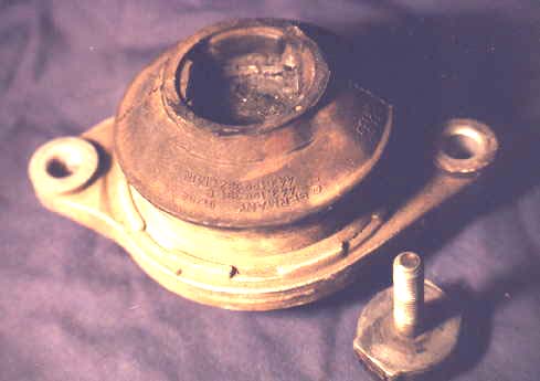
Engine Mount (Hydraulic) Testing
In 1985 Audi introduced hydraulic engine mounts on the 5 cylinder engines, here is a diagram showing a cross section of the mount.
The hydraulic mount acts as a shock absorber, it has two chambers, filled with water/alcohol mixture along with a spring steel diaphragm. The two chambers are separated by a metering plate.
If the mount is subjected to slow or low frequency movement, the fluid will easily move between through the metering plate between the two chambers, and the mount will be soft for improved noise and vibration damping. With quick or high frequency movement, the metering plate will restrict the fluid movement between the two chambers and will behave stiffly to prevent excessive drivetrain movement.
The two hydraulic engine mounts and the rear transmission mounts should be checked and replaced if necessary, the exhaust side (passenger side) engine mount on the Turbo Audis is subjected to a lot of heat.
If your car has over 75k miles, I would recommend you replace the original engine and transmission mounts.
Check that the hose from the oil cooler air scoop is installed correctly as it provides cooling air to this mount. Also check the condition of the rubber washer cap over the engine mount that helps deflect the air correctly.
A defective hydraulic engine mount on this passenger side tends to place more stress on the exhaust manifold/system.
One way to check the engine mounts is to support the engine using a floor jack under the oil pan and then loosen and remove the lower two nuts on the mount you are checking, the lower part of the mount will drop down from the hydraulic action of the mount, if the mount drops down and flops around and offers little resistance to being pushed back up then the internal hydraulic portion of the mount is dead.
Another possibility that will cause the mount to flop around after being lowered is if the upper rubber section is broken free from the upper mounting stud. You may want to pull down on the mount to see if the upper portion breaks loose. This happened on the right side mount from my 89 200TQ as shown here.
As mentioned, you may want to replace the rear transmission mounts as well, they tend to sag over time especially if they get doused with some Pentosin P/S fluid from a leaking steering rack.
References: [2] Audi 100, 200 Official Factory Repair Manual Volume 1, Robert Bentley Corporation [5] Audi of America service publication: 1985 Model Change information Copyright © SJM Autotechnik™ , all rights reserved
Return to Troubleshooting Tips page. Return to SJM Autotechnik™ main page.
|
| About Us Privacy Policy Terms of Use Links Customer Service Safety Information Home |
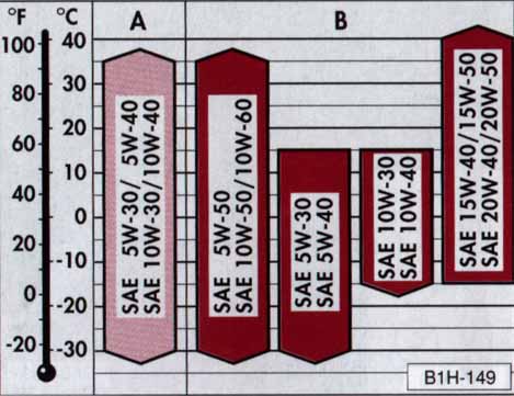
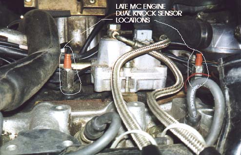
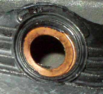
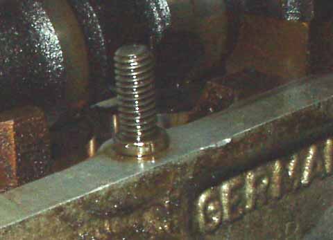
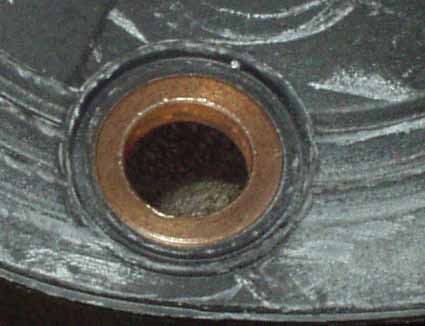
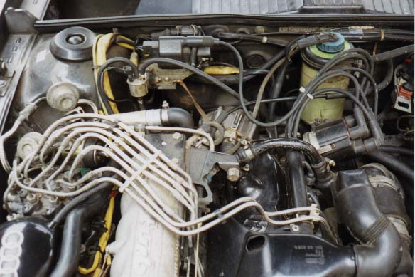
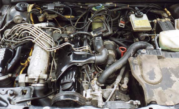
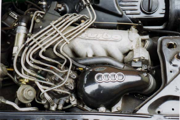
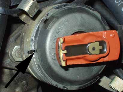
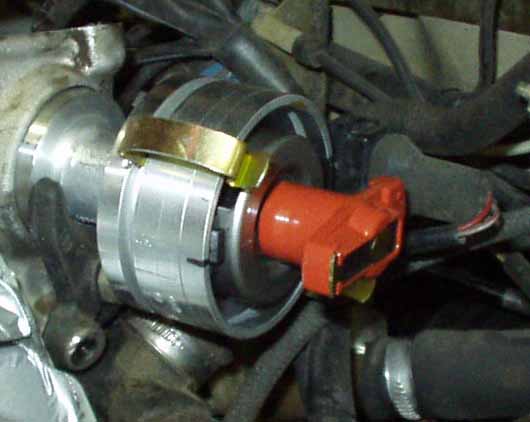
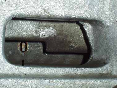
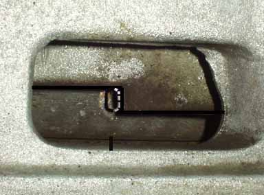
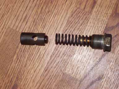
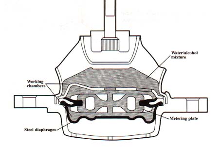 Diagram courtesy of Audi America