|
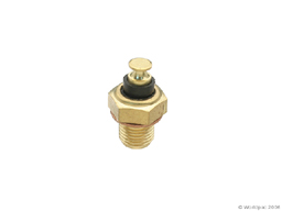
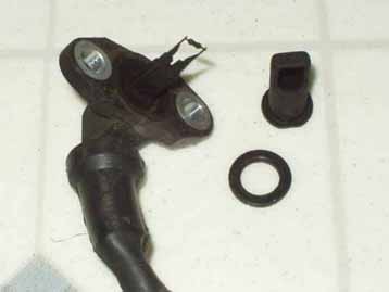
Cooling System, Technical Tips, 1986-91 5000/200TQ Some information applies to the 1992-95 Audi 100/S4/S6 Important Safety Information After-Run System: Turbo Electric Water Pump, Coolant Hoses The Turbo charger has separate coolant supply hoses as well as oil supply lines. When the engine is running, coolant flows from the engine block, enters the lower end of the turbo, then comes out the top and is routed through a pipe behind the timing belt cover, which then connects to the coolant flange on the cylinder head. The coolant flows through the top radiator hose and back to the radiator for cooling. When the engine is shut off, and the engine coolant temperature at the exit of the cylinder head is above 110C, (230F) a secondary electric water pump turns on, which provides circulating coolant through the top coolant line down into the turbo and then into the engine block to ensure any bubbles from the boiling coolant get purged. The circulating coolant helps keep the turbo center housing temperature down at a reasonable level to prevent coking of the oil in the turbo housing. The electric coolant pump is controlled by the after-run temperature sensor and the after-run control unit. When the Turbo cooling pump is turned on, the low speed radiator fan is also turned on by the after-run control unit. For details on the operation and location of this sensor, go to After-run system section below. 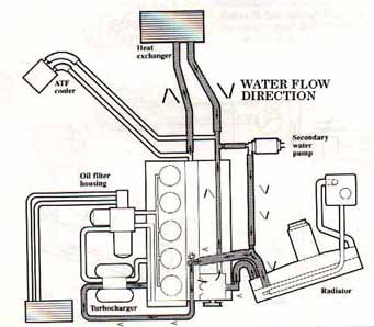 Note: When the engine is running, the coolant flow is reversed, coming out the top of the turbo and then over to the top radiator hose connection on the block. This electric coolant pump and connecting hoses are often over looked and can fail at the most inopportune time. See below for details on the turbo cooling pump and after-run temperature sensor. CAUTION:The Turbo secondary electric water pump has plastic fittings which can break off while working under the hood if you bump into the pump fittings and this can spray HOT BOILING COOLANT on you causing severe burns. I have had the "pleasure" of experiencing this and have the burn scars to prove it. WEAR SAFETY GOGGLES and PROTECTIVE CLOTHING while working around a hot engine! The radiator fittings are also plastic and these can break off while working around the engine. You may want to remove the pump and test it in a bucket of water to make sure it is still pumping. The pump uses a magnetically coupled impeller which can seize up, or fall apart as they get older. Use some jumper wires to apply 12V DC to the pump while you stick it down in the bucket of water. The pump has markings near the connector showing the positive + and negative - (ground) connection. There are two metal coolant pipes that are used to connect to the turbo and provide coolant into and out of the turbo. These metal coolant pipes have rubber hoses on each end where they connect to the engine cooling system. On the 5 cylinder 10V engines, one of these hoses connects with a banjo fitting to the cylinder head coolant outlet. On the 5 cylinder 20V engines, there is a rubber hose that connects from this metal pipe to the coolant manifold on the cylinder head underneath the intake manifold. On both the 10V and the 20V engines the other turbo coolant pipe connects to the engine block core plug with a special rubber/Teflon jacket hose. Check this hose for any leakage or failure. On the 10V engines, the OEM rubber hose and fitting can be purchased from the dealer for big $$, or you can replace it with some high temperature silicone or coolant bypass hose. The 20V turbo rubber hose can be replaced with a straight section of the appropriate sized coolant hose often found at many auto parts stores in molded shapes for other make vehicles. We also carry the correct Audi specified Hose for this application. Fuel injection hose could also be used in an emergency, but it won't last very long and will get hard quickly from the high temperature. On the 10V engine hose, the swedged on clamp can be ground off or cut off using a hacksaw and then a conventional hose clamp and high temperature coolant hose can be installed. The same can be said for the hose that connects the metal turbo coolant pipe to the side of the engine block to the freeze plug nipple. This pipe can be removed and the hose can be replaced but you may want to consult with a hose specialist and find some high temperature hose to replace it. The original hose looks to have a Teflon liner inside the rubber hose. The freeze plug (core plug) with the nipple on it, should be checked for excessive corrosion and replaced if necessary. After-run Temperature-Sensor and After-Run Control Relay 1986-91 5000/200 Turbo and Turbo Quattro 1992-95 Audi S4/S6 As mentioned, the turbo engines have this nice system where the turbo cooling pump and the low speed radiator fan come on for several minutes after the engine is shut down. Most engines will experience a rapid rise in coolant temperature after the engine is shut down as the heat in the engine block, cylinder head, and from the turbo hot side is transferred into the coolant. The 1992-95 Audi S4/S6 cooling system with the engine driven fan tends to control the coolant temperature better, so you may not hear the after-run system turn on as often. The normal test to check the after run system which turns on the turbo cooling pump and low speed radiator fan, is to run the engine at idle until the normal radiator fan comes on (2nd speed), then immediately shut off the engine. The low speed radiator fan and turbo pump should turn on within about 5 minutes. If they do not turn on, remove the two wires from the after-run temperature sensor (see photo below to identify this thing) and connect the wire terminals together, now with the wires connected together to bypass the sensor, the low speed cooling fan and turbo cooling pump should be turned on. You can also pull down the rubber boots on the two spade terminals on this after-run temp sensor and short across the terminals with a small metal screwdriver without removing them. If you remove the two wires, avoid shorting them to ground, or you can blow the fuse for this circuit. The ignition does not have to be turned on, as this system should be working with the engine/ignition off. On the Five cylinder turbo engines (10V) the After-Run Temp sensor is mounted on the cylinder head upper coolant outlet pipe that directs water to the radiator. Check out the photo below 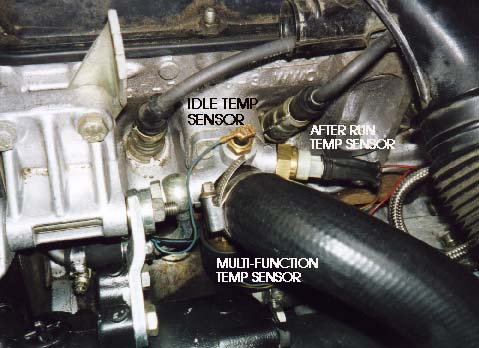 This after-run temp sensor is used in conjunction with the after run relay (control unit) to turn on the low speed fan and turbo cooling pump. The after-run relay will limit the time (8-10 minutes) the low speed fan and turbo cooling pump will run, to avoid running down the battery if the temp switch should fail. The 1991 200TQ 20V and S4 Turbo engine use the same after-run temp sensor but it is mounted upside down on the cylinder head water outlet pipe below the intake manifold. Again, check the photo below for details. 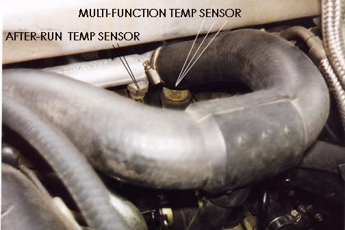 1991 200TQ 20V Engine view of the after-run sensor and MFTS This after-run temp sensor is designed to turn on the low speed radiator fan and turbo coolant pump when the coolant at the sensor reaches 110 degrees Celsius (230F), the sensor will turn off the after-run system when the coolant temp drops down to 97 Celsius (207F). The sensor is also designed NOT to work above 130C to avoid any problems, I suppose, if a fire should start in the engine compartment. If the low speed fan and turbo coolant pump don't come on when you connect the After-run temp Sensor wires together, check fuse #21 (25 Amp) as this supplies +12V to the turbo cooling pump and to the temp switch. Also check the wiring at the connector on the after run pump, as some vehicles provide +12V to the temp sensor via this connection. The 1992-95 S4/S6 uses a different fuse or in some cases a circuit breaker, so you may need to hunt around to find it. You can heck your owners manual or Bentley Repair manual for the fuse number and location, but it usually doesn't show this circuit. One 1992 S4 I checked had this After Run fuse/circuit breaker located next to the After Run control unit in the Aux III panel, behind the passenger side kick panel. The fuse/circuit breaker holder or socket should have a white/black wire and one or two red wires connected. If you use a +12V test light, or DMM, there should be +12V on one of the wires (R/BK) connected to this temp switch and there should also be +12V on the same colored wire (R/BK) connected to the Turbo Pump. This fuse also supplies +12V to the injector cooling fan relay. If the after-run system fuse is ok, and you have +12V on the Red/Black wire connected to the temp sensor and on the Red/Black wire at the turbo cooling pump, and connecting the temp switch wires together does NOT turn on the Turbo coolant pump or low speed radiator fan, then the after run relay and low speed fan relay/wiring should be checked. AFTER RUN RELAY (CONTROL UNIT) LOCATIONS 1986-88 5000T/Q models. The After-run relay is mounted under the drivers side dash area on the aux relay panel. On the 5000T/Q the small access panel or the lower dash cover panel can be removed to gain access to this relay. For the 10V 1989-90 200TQ's, and 1991 200 Turbos (FWD), it is usually behind the left side kick panel below the hood release lever, and the kick panel needs to be removed (pain in the butt). For the 1991 200TQ's with 20V the after-run relay is in the aux relay panel under the drivers side dash board area, the knee bar usually needs to be removed on these. A mild pain in the rear. See this section for details. The 1992-95 Audi S4/S6 has the after run relay located behind the passenger (right) side kick panel on the aux relay panel III. See photo below The same part numbered after run relay (control unit) is used by the 1986-88 5000T/Q, 1989-91 Audi 200TQ and the 1992-95 S4/S6. 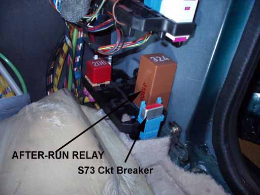
In some cases the internal components (transistor or resistor) inside this after-run control unit get burned up on older high mileage vehicles and this may cause the after run fan or turbo cooling pump to run all the time even with the ignition off which will certainly kill your battery in a short time. Unplugging the after-run control unit should stop the fan or cooling pump from running continuously if the control unit is defective. It is a GOOD idea to have the Bentley wiring diagram with you while you trouble-shoot the after run relay or wiring, as there are some subtle differences between the 5000T/Q, the 200T/Q and the 1992-95 Audi 100/S4/S6 with regards to the A/C and cooling system operation. The Bentley manual wiring diagram for the 1992-93 S4 seems to be missing the after-run system wiring and component information. One 1992 S4 I checked had this After Run circuit breaker located next to the After Run control unit in the Aux Relay Panel III as shown in the above photo (S73). This Aux Relay Panel III is behind the passenger side kick panel. The fuse/circuit breaker holder or socket should have a white/black wire and one or two red wires connected to it. The 1994 S4 and 1995 S6 may use a different numbered fuse or circuit breaker other than #S73, check the Bentley wiring diagram for details. The following tests were done on a 1987 5000TQ with the After-Run-Relay removed, and will check the wiring to the after-run relay. I have listed both the terminal numbering for the connector socket as shown in the Bentley manual, and the terminal numbering that is shown on the after-run relay itself. With the two wires on the temp switch connected together, and the After-run relay removed, you should see +12V at terminal 2 in the connector socket (Terminal 30 pin on the after-run relay). If you do not have +12V at Terminal 2 with the temp switch wires connected together, there is a wiring problem between the temp switch and the after run relay connector socket. Terminal 6 on the connector socket should be grounded to the vehicle body. (Terminal 31 on the after-run relay). Terminal 8 on the connector socket connects to the turbo coolant pump (BR/BK wire), (Terminal 87 on the after-run relay) and normally the after-run relay grounds this terminal to turn on the turbo coolant pump when the temp switch wires are connected together. When you use a jumper wire and ground this Terminal 8 connection, the Turbo pump should start running. If the pump doesn't run when you ground Terminal 8, you either have a wiring problem between the pump and the connector socket, or a dead turbo pump. You should remove the turbo cooling pump and try applying +12V and ground across the two terminals to see if the pump is turning. You can also place the pump in a bucket of water and see how well it pumps. Terminal 5 on the connector socket (Terminal 87A on the after-run relay) normally provides a ground to the 1st stage radiator cooling fan relay (#6) in the main fuse panel under the hood "when" the temp switch wires are connected together and the after-run relay is working. If you ground Terminal 5 in the connector socket, the 1st stage radiator fan should turn on. Terminal 4 (Terminal 15 on the after-run relay) gets +12V when the engine is running from the fuel pump relay (Terminal 87A). If all of the above tests work as expected, and the Turbo pump and low speed fan come on when you jumper across the connector socket, the after-run relay is not working and should be replaced. NOTE: The turbo pump is tough to tell when it is running, sometimes (CAREFULLY IF HOT) placing your hand on the pump you can feel it running. This pump has a magnetically coupled impeller inside and it is not cheap to replace if it is leaking or if it stops pumping. If you are not sure if it is working, you may want to remove the pump when the engine is cool and test whether it is pumping correctly by applying +12V while the pump is in a bucket of water. USE EXTREME CAUTION WHEN WORKING AROUND A HOT ENGINE, AS THESE PLASTIC TURBO COOLANT PUMPS CAN BREAK AND SPRAY HOT SCALDING COOLANT CAUSING SEVERE BURNS. Auto-Check System: Cooling System Overheat Temperature Warning Indicator The Auto-Check System display (OK displayed on start up), will give you a beep warning and show the display picture with the little thermometer, whenever the coolant level is too low in the expansion reservoir OR if the engine is overheating with a coolant temperature above 119 C, (247F). The fluid level sensor in the bottom of the coolant expansion reservoir will close and connect the Auto-Check circuit connection to ground if the coolant level drops too low in the reservoir. In some cases the electrical connector terminals will corrode for this level sensor, and cause a false signal to the Auto-Check system. Removing the connector at the bottom of the coolant reservoir, should stop the coolant level warning, if there is a problem with the coolant level sensor. You need to restart the engine after unplugging the sensor during this test. The Multi-Function Temperature Sensor (MFTS) described below in more detail, uses terminal 4/C to ground the same circuit as the coolant level sensor to also signal to the Auto-Check system when the coolant temperature in the cylinder head gets too high. These sensors can be a 4 terminal model made by VDO or a 3 terminal model made by Behr. As of October 2003, the 4 Terminal VDO brand is no longer available, if I find another source for this 4 terminal sensor, we will let you know. I found that a some of the replacement 3 terminal replacement Multi-Function sensors I purchased for my customers vehicles failed after 1-2 years and gave a "false" overheat signal to the Auto-Check system. See next section below for more details. I may have received a bad lot of these way back in 2002, but have not seen this problem since that time. Terminal 4/C on this MFTS provides this overheat ground signal to the Auto-Check System. Unplugging the 4 terminal connector to this MFTS will eliminate the Auto-Check overheat symbol if you think you have a defective sensor. You need to shut the engine off, disconnect the sensor connector and then restart the engine during this test. The Auto-Check system appears to have some time delay built in, that prevents the system from immediately responding when the sensor is unplugged or reconnected. A Fuse supplies +12V to the Auto-Check control unit and to the MFTS (4 terminal VDO version) on some model years, so check the applicable fuse for your model vehicle if you have the 4 terminal sensor in use. Coolant Types for VW/Audi G 001 100 or ZVW 237 104 "Blue" non phosphate coolant is specified for the majority of the VW and Audis built before 8/1996. This is what we recommend and use in all Audis prior to 8/1996 production. As of 8/1996 later VW/Audi vehicles use the "RED" Lifetime fill coolant Audi G012 A8D A1 or the VW Part number ZVW 237 G12, but this coolant has been superceded several times, so make sure the coolant you select is correct for your Audi. See Service Bulletin Information below. The following information is from a Service bulletin issued by Audi of America: Group 19 Number 96-01 Date: Oct. 30, 1996 Production: A new coolant, G 012 A8D A1 is being used in production as of 08.96. G 012 A8D A1 is red in color This newly developed product permits a cooling system fill that lasts the service life of the engine and was designed with all aluminum engines in mind. Advantages: Improved corrosion protection Improved thermal stability Improved Heat transfer/control Improved Hard Water tolerance Improve environmental protection Caution: G 012 A8D A1 is the only coolant to be used in the Audi A8. Use of any other coolant will result in engine damage. Caution: G 012 A8D A1 must NEVER be mixed with ANY other coolant. Engine damage will result. Contamination of G 012 A8D A1 with other colored coolants is identifiable by discoloration (brown, purple, etc). This mixture causes a foamy deposit to appear in the expansion tank/radiator. This contaminated mixture should be drained immediately and the cooling system flushed as described below. Flushing procedure: Engine at operating temperature, with heater on. Drain coolant, see repair manual, General Engine, group 19 Apply compressed air to expansion tank to blow out remaining coolant Close cooling system, fill with distilled water Run engine for a minimum of 2 minutes Drain water and apply compressed air to expansion tank as before Close cooling system and fill with appropriate mixture ratio of G 012 A8D A1 and distilled water Test Drive, check coolant level and add if necessary. Note: G 012 A8D A1 coolant "may" be used in older vehicles when the original coolant is drained and cooling system flushed as described above. Always inform customer that a new coolant is used and that ONLY water or G 012 A8D A1 be used to replenish. End of Audi Service Bulletin:
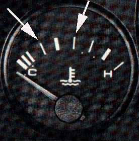
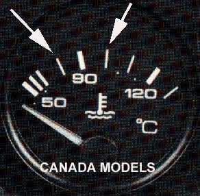
Coolant Temperature Gauge-Overheat Warning:
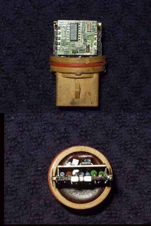
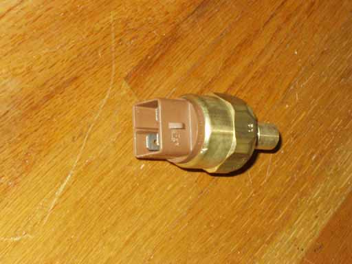
Multi-Function Temperature Sensor (MFTS) Audi also refers to this as the "Electronic Thermoswitch"
in the wiring diagrams and the "Water Temperature Sensor"
in most parts catalogs.
If you have the original 4 terminal VDO brand sensor, make sure the
+12V wiring connection (3/+) has power. You could have
a blown fuse, check the wiring diagram for your vehicle. Terminal 2/R also provides a ground signal from this same connection to the A/C control head unit which also will turn off the A/C if the engine temp. exceeds 247F. If your engine is not overheating, and you suspect the sensor is malfunctioning,
you should test this terminal 2/R connection (Blue wire with green stripe)
to ensure that it is not grounded by the sensor, from faulty wiring,
or from corrosion. WIRING COLOR CODES Connection problems: In some cases the connector terminals
can be corroded and will be causing a poor connection. The rubber boot
that is supposed to protect the connector, often times gets old and
hard and allows water/coolant to fill up the rubber boot and saturates
the connector terminals and can cause corrosion problems. MFTS: Design Info Engine Control Unit (ECU) Coolant Temperature Sensor Information on these single wire temperature sensors is located HERE
Engine Control Unit (ECU) Air Temperature Sensor Information on this Air Temperature sensor is located HERE
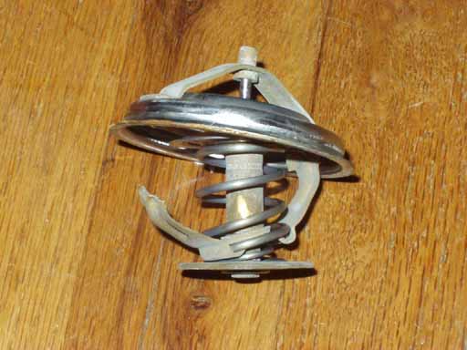
Cooling System Hoses, Thermostat and Heater
Valve Install the thermostat with the cross brace vertical, orientated
at 12 and 6 O'clock Water Pump Replacement Many of the Audi/VW water pumps will seep a small amount of coolant out of the "weep" hole at the bottom of the water pump, this is considered normal and nothing to be concerned about. Of course if a large amount of coolant is leaking out, the pump shaft seal is shot. Note that there was a change in 1989 to the use of a different timing belt with a rounded tooth "Super Torque Belt" and the water pump/pulley assembly changed at the same time. The cam and crank timing belt gears are different as well. Make sure you don't install the wrong water pump or wrong timing belt on the 1989 and later vehicles. Go to the Engine section for details on replacing the water pump and timing belt. Radiator Electric Fan Not Running 1990-91 Audi 100/200, 1992-95 Audi 100/S4/S6? Check the Fusible Link or Blade Type fuse. Retrofit on older 5000/100/200 vehicles The 1990-91 Audi 100/200TQ's added a fusible link which fuses the ground side of the cooling fan motor. This fusible link is located inside a small black plastic housing with a cover that pops up which is mounted next to the coolant over flow tank. The following photo shows this fusible link with the black cover removed. 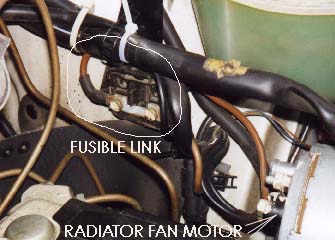 The radiator cooling fan motor on the 5000/T/Q and early 1989-90 100/200TQ have a nasty habit of causing a complete meltdown of the wiring harness if the fan motor bearings seize up which creates a huge current draw from the fan motor. This fusible link and plastic mounting box can be added to the early model cars to prevent a problem should the fan motor seize up.
I used two 10 gauge wires in parallel to connect from the fuse box to the fan motor ground lug. The original ground wire from the fan motor can be connected to the fuse box. The Audi V8 uses a similar fuse arrangement for the radiator fan and this is mounted inside the engine compartment on the left front fender area behind the head lamp area. The Littel fuse catalog shows some fusible links for Mercedes applications that look to be the same size/shape as the 80A Audi N 017 125 3 fusible link. The catalog shows that 30, 50, 80, and 100 Amp versions are available. The 80A Littel Fuse part number is FBM 080. Volkswagen used a 50A version of this fusible link N 017 125 1 in some of their Diesel applications, so double check that you get the 80A as these small parts sometimes get mixed up in their bins at the warehouse. Many Auto parts stores now sell larger bladed type fuses rated from 20-80 A and large heavy current fuse holders which can work in this application. One example is the "MAXI Blade Fuse" rated at 80 A that is available from Littel fuse as the "MAX 80" part number along with the "MAH 1" in-line MAXI fuse holder with 6 gauge wire. The initial start up current for the 500 Watt radiator fan motor can be fairly high >50-60 Amps and I believe this is the reason for the use of the factory 80 amp fusible link even though the steady state current is only around 35-40 amps. The later 1992-95 Audi 100/S4/S6 has a large blade type 60A fuse located inside the car on aux relay panel II which is the relay panel underneath the lower left kick panel on the drivers side next to the hood release. Radiator The Plastic radiators on these cars usually have a problem as they get old after 10-12 years where the upper radiator hose outlet gets fragile and snaps off. Over tightening the radiator hose clamp can make this occur as well. There was a factory bulletin that outlined a procedure to repair the broken neck with some epoxy but you are better off replacing the radiator than relying on this method of repair. If your after-run system is not working, this can help cook these plastic radiators after engine shut down and destroy the top plastic outlet a little sooner. The small over flow hose fitting is also very fragile and can break off as the plastic gets brittle over time. Be extremely careful when replacing this small hose. It helps to carefully cut through this small hose end with a razor knife to relieve the tension on the small fitting as you try and remove the hose. The factory replacement hose is made with silicone rubber to withstand the extended high temperatures. On high mileage vehicles with the original radiator, I have also seen the plastic side tanks split open and fracture and in other cases the aluminum side clamps can break and cause leakage at the side tanks. The replacement OEM Aluminum and plastic radiators give some piece of mind to avoid this type of failure on high mileage vehicles and will normally give another 10+ years of life. As mentioned previously, I would recommend replacing the upper and lower radiator hoses as well as the thermostat if your vehicle has over 100k miles on it to help prevent a breakdown on the road. The 1991 200TQ 20V with the auxiliary radiator has two extra fittings on the side tank in the radiator which makes the replacement plastic/aluminum radiator "unique" for this one year vehicle. RADIATOR REMOVAL and REPLACEMENT: The plastic shroud/cover needs to be removed that is in front of the radiator, remove the 2 Phillips screws and one 10mm plastic nut. The upper radiator support mount with bracket on the left is removed, as well as removing the nuts from the rubber mount on the right side top. The condenser in front of the radiator has 2 bolts/nuts, then you need to pull up on the condenser slightly to get the condenser lower metal bracket up and then move it forward out of the radiator recess. With the engine cool, remove the lower radiator hose to drain out the coolant, have an appropriate container to catch the coolant so you can dispose of it properly. On the radiator fan switch pull back the rubber boot slightly and then pull the connector out. Remove the upper radiator hose, and the aux radiator hoses on the 20V's. I leave the radiator fan/shroud on the radiator in place on the radiator and remove the wiring from the fan motor and after-run pump and carefully push the after run pump through the rubber supports a little to get it out of the way. You may need to tie these wiring harness out of the way to avoid catching them on the fan motor. Remove the coolant reservoir 3 Phillips screws, the reservoir electrical sensor connector plug, and remove the hose from the bottom of the reservoir. At the bottom of the radiator, the 5000's and early 100/200's have 1 lower rubber mount, the 1990 and later 100/200's and 1991 200TQ 20V's usually have two lower rubber mounts. You need to remove the 13mm hex nut(s) with washer, as well as the two 10mm bolts with washers that secure the plastic air ducting to the bottom of the radiator. There is also plastic clip on a wiring harness that needs to be popped loose from the plastic radiator fan shroud down from below. You need to either remove the fender liner on the driver side or remove the power steering pump to allow tilting the radiator for removal upward. If you remove the P/S Pump, on the 5000/100/200's with 10V engine, you can leave the hydraulic lines on the pump, and just unbolt the pump and carefully swing it up over the valve cover area and use some wire to hold it away from the radiator area. For the 1991 200TQ 20V's, it is easier to remove the fender liner, otherwise you need to remove the P/S pump completely. If you decide to remove the P/S pump anyway to allow getting to the other cooling hoses down below, you should clamp off the suction side hose to prevent loosing all the fluid, then remove the 3 banjo bolts, and unbolt the brake accumulator metal line from the back of the pump and remove the hoses/lines from the pump. Put the hose ends in a plastic bag and tie them up and out of the way over the intake manifold area. On the pump, remove the pivot and adjustment nuts/bolts, pull the belt off the pulley and then remove the pump while avoiding spilling too much fluid. With the p/s pump out of the way, or with the fender liner removed, this allows swinging/rotating the radiator up to the left and out from underneath the fender area. Now you can remove the lower 10 mm bolts and upper 10mm bolts on the fan shroud. While you have the radiator out of the car, you should replace the lower radiator mount(s), the 2 upper rubber mounts, the radiator fan switch, the lower radiator hose, the short hose behind the thermostat, and the turbo cooling hose connected to the metal pipe. You can also replace the coolant reservoir hose, upper and lower while you are in there. If you have not done the thermostat in the last 2 years, replacing it is a good idea. You can flush out the system with the thermostat removed, and by removing the rear hose at the back of the cylinder head which connects to the heater valve. When installing the radiator you need to be careful not to smash or damage the small reservoir fitting that is under the fender area. 3 Speed Radiator Fan, Radiator thermoswitch, Fan Relays, Fan Tests This information applies directly to the 1986-88 Audi 5000T/Q, 1989-91 Audi 200T/Q. Some information applies to 1992-95 Audi 100/S4/S6 but check your wiring diagram to verify. NOTE: The 1990-91 Audi 100/200 added a fusible link (80A) for protecting the radiator fan wiring which is located in the engine bay below the coolant reservoir. Check the fuse section above for details. The 1992-95 Audi S4/S6 used a 60A large blade type fuse that is located in the front area on the Aux relay panel II. This Aux relay panel II is located underneath the dash on the drivers side, underneath the lower left kick panel. The radiator cooling fan is setup to have 3 operating speeds, low speed (1) when the A/C is turned on and also when the after run relay is turned on after engine shut down. The 2nd speed is used most of the time when the dual temperature radiator thermoswitch activates at the lower turn on temperature. NOTE: The Bentley manual describes this thermoswitch as controlling the 1st and 2nd speed radiator fan, but the Bentley does not include the lowest speed of radiator fan operation, which occurs when the Air conditioning (A/C) is in operation and also the low speed when the radiator fan operates for a short time after the vehicle is shut off (after-run fan). If you include this lower speed radiator fan operation, the two temperature radiator thermoswitch actually controls the 2nd (medium) and 3rd (high) speed radiator cooling fan. The 2nd speed fan uses a relay underneath the hood in the main fuse/relay box. The 2nd speed fan can also come on from the action of the A/C high pressure switch, as the high side pressure increases enough and requires more heat transfer over the condenser, so the 2nd speed fan is required. The 3rd speed or HIGH speed or "JET ENGINE ROAR" speed is controlled by the two temp radiator thermo switch and a 70 amp relay underneath the driver side dash panel. 1992-95 Audi S4/S6 have all 3 relays located in the main fuse/relay panel under the hood. When the high temp portion of this switch is turned on, the relay is actuated and full battery voltage is sent to the radiator fan for the 3rd or high speed operation. Please note, that if you find you have some burnt 2nd/3rd speed relays, or wiring, you may have a dying radiator fan motor that is drawing too much current and overloading the wiring and relays. You may also have some loose wiring connections at the relays, which can cause the wiring/connections to overheat during heavy current draw. See below for details on installing the radiator fan fusible link, which may help prevent wiring/relay damage or electrical fires when the radiator fan dies or seizes up and causes a huge current draw on the wiring/relay system. 2ND AND 3RD SPEED RADIATOR FAN TESTING NOTE: If the Thermostat doesn't open completely, there won't be enough water flow through the radiator which can cause overheating. It is also possible that there won't be enough hot water flowing to allow the radiator fan switch at the bottom of the radiator, to heat up and turn on the radiator fan. One way to test the 3rd or High Speed operation of the radiator fan, is to "temporarily" remove the 2nd speed fan relay from the fuse/relay box under the hood, and let the engine idle until the High Speed fan turns on. Keep an eye on the coolant temp gauge to ensure the car doesn't overheat during this test, if the high speed fan never turns on. Make sure you re-install the 2nd speed fan relay after doing this test. As mentioned, the radiator has a three terminal thermoswitch (temp sensor switch) that switches for two different temperature ranges. This thermoswitch is screwed into the lower part of the radiator tank just below the bottom radiator hose connection. Here is a photo showing this switch with it removed from the radiator. 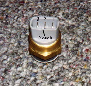 Terminal 3 receives +12V via fuse S15 (25 Amp). Terminal 1 connects to the 3rd speed relay, and when the thermoswitch closes it provides +12V to turn on this 3rd stage relay which sends full +12V to the radiator fan motor. Terminal 2 connects to the 2nd Stage Relay and when the thermoswitch closes it provides +12v to turn on this 2nd stage relay which sends +12V to the resistor pack (E2 to E3) to drop some voltage for the 2nd speed fan operation. (See Below for details on testing the resistor pack) NOTE: This thermoswitch terminal numbering corresponds to the Bentley wiring diagram, but be aware that some of these thermo switches are marked inside by the terminals, from left to right as + 2 1 which can be confusing. If you remove the electrical connector from this thermoswitch, here is the corresponding terminal numbers that match the numbering I used in the photo of the thermoswitch. 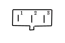 To test the 2nd and 3rd speed operation, use a jumper wire across this connector, first jumper across Terminal 3 and 1 with the ignition turned on, the fan should come on high or 3rd speed assuming the 3rd speed fan relay and wiring are ok. If you insert the jumper wire across Terminals 3 and 2, the fan should come on medium or 2nd speed provided the ignition is turned on, the 2nd speed fan relay and wiring are ok and the radiator fan resistor pack is ok. (See details below for testing the radiator fan resistor pack). If the fan does not come on during the above 2 tests, connect a 12V test lamp across the radiator fan motor connections and do the 2 tests again. The test light should come on during the tests to indicate the 2nd and 3rd stage fan relays and wiring are ok. If the test light does not turn on, use the Bentley to check the wiring and 2nd and 3rd stage radiator fan relays. If the fan doesn't run but the test light is coming on during the two tests, the radiator fan motor is likely kaput but do the following test to be sure. RADIATOR FAN TEST One basic test you can also do for the radiator fan motor, is to connect +12V to the radiator fan motor directly from the battery jumper post to see if it spins. You should first disconnect the positive wires on the fan motor (tape them to avoid shorts during the test) and use some heavy gauge wire (8 or 10 gauge) or a Battery jumper cable to connect to the fan motor. You should make sure the fan spins freely and does not have seized bearings before trying to jump start it or the jumper wire could suffer a melt down. The fan draws about 40-50 amps during initial start, so expect some serious sparking when you first connect the jumper wire. Be sure to keep your hands away from the fan blades during this test. If the fan doesn't run, you can also connect a 8 or 10 gauge wire or jumper cable from the engine block to the ground side of the fan to ensure the fan is getting a good ground connection. On the later 1990> Audi 100/200's with the fusible link for the fan ground wire, I have seen this fusible link get cracked or have excessive corrosion on the terminals which prevented the fan from working at all. RADIATOR TEMPERATURE SWITCH INFO The 10V Turbo and 20V turbo specify the same part number for this switch. This switch specifies a turn on temp of ~95 C for the 2nd speed fan, turn off at ~84C. The fiche shows the turn on temp of ~102C for the third speed radiator fan, turn off at ~91C. I have noticed that some aftermarket replacement sensors are available that operate the radiator fan at lower turn on temperatures (85C and 93C respectively) but I don't generally recommend using these, as the cooling system should work fine under all temperature conditions if the correct coolant mixture ratio is used, and everything is operating correctly. On my own 1989 200TQ I found my gas mileage dropped 2 MPG when using this lower temp radiator fan switch. Some people have chosen to use these lower temp radiator fan switches because they live in a very hot climate area and they want to reduce the underhood temperatures. In a few cases when this two temp thermoswitch acts up and is defective, the 2nd speed radiator fan will come on for a short time and then go off. In other failure modes, the radiator fan switch will short on all the time, and keep the radiator fan running whenever the ignition is on. The fan can also stay on due to a faulty 2nd or 3rd stage relay if the internal relay contacts get welded together. RADIATOR FAN RESISTOR PACK TESTS If the 1st or 2nd speed fan is not coming on, you may want to check the large resistor pack with aluminum heat sink mounted down below the front of the radiator on the frame. This large resistor pack is used to drop the voltage to the radiator fan motor to provide the 1st and 2nd speeds. Often times the 2nd speed fan will stop working due to this resistor pack getting burned up. Here is a photo of this resistor pack that is used on the 5000/200T/Q with it removed from the vehicle frame location. The S4/S6 has a similar resistor pack on the side of the drivers side frame rail. 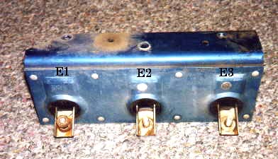 The 3 Terminals on the resistor pack are designated E1, E2, and E3. On the 87-88 5000T/Q, E1 should have a Red/Brown stripe wire, E2 should have a Red/Blue stripe wire, E3 should have a Black/Red Stripe wire. The 89-91 200TQ shows E1 with a Red wire, E2 with a White wire, and E3 with a Black or Black/Red stripe wire. Check your wiring diagram for the 1992-95 S4/S6 vehicles for any changes. The resistance from E2 to E3 is only ~0.2 ohms and the 2nd speed fan current flows through this resistance and drops some voltage for correct 2nd speed operation, the resistance from E1 to E2 is also ~0.2 ohms. The resistance from E1 to E3 is ~0.4 to 0.5 ohms and this measurement goes through two resistance's (E1 to E2, then E2 to E3) which are used to drop more voltage for the 1st speed (low) radiator fan. If the resistance element from E2 to E3 burns up, you will lose the 1st and 2nd speed operation, if the resistance from E1 to E2 burns up, only the 1st speed (low) will stop functioning. Accurately measuring a small resistance value on this resistor pack is difficult as it requires an accurate Digital Multimeter (DMM) and requires you to zero out the resistance of the test leads. If you measure a high resistance or open circuit between E1 and E2 or between E2 and E3, you can be pretty confident that the resistor pack is defective. OTHER NOTES: 5000TQ: The 2nd speed fan can also get stuck on due to the relay contacts getting welded together, there was a service bulletin issued about this problem. Whenever the ignition key is off the 2nd speed fan should NOT be running. Only the low speed fan should come on from the after run relay when the ignition key is turned off. If only the low speed fan is "not" working when the A/C is turned on, check the relay in position #6 under the hood in the main fuse box. Also check the After-run relay and wiring, as the 5000T/Q uses this relay to turn on the low speed when the engine is running and the A/C compressor is activated. 1989-91 200TQ, and 1992-95 S4/S6, check the wiring diagram for any changes. S4/S6 Serpentine Belt Tensioner Failure If you are hearing any growling or bearing related noises when the engine is running, you may want to check the Serpentine Belt Tensioner pulley bearing. These can fail and if they seize up the Serpentine belt can get torn up and make a mess in the front of the engine. 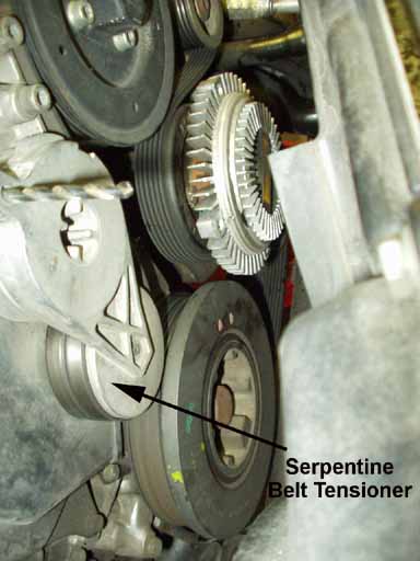 You can use an adjustable crescent wrench to grip the top of the tensioner and twist the tensioner to the right, and then insert a round pin or drill bit in to the hole in the front of the tensioner, to hold the tensioner in the relaxed position. Then you can remove the 3 allen bolts that hold the tensioner assembly to the front of the engine and remove the assembly to check the bearing for looseness or noise when you spin the tensioner roller. It is our understanding that the roller bearing itself is not available, and the entire tensioner needs to be replaced. S4/S6 Engine Driven Fan Viscous Coupling Failure The 1992-95 Audi S4/S6 uses an engine driven cooling fan which utilizes a Viscous Fan coupling that changes the speed of the fan depending on the outside temperature and temperature of the air flowing through the radiator and A/C condenser. 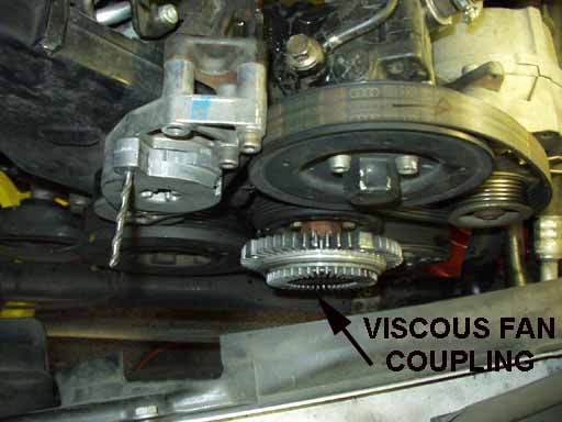 The Viscous Coupling can wear out and have too much side to side play which allows the plastic cooling fan to hit the power steering pump pulley and break the plastic fan blades off. These broken plastic fan pieces can then get jammed into the radiator and pierce the radiator core and cause coolant leakage. This leads to a very expensive repair! According to the Bentley repair manual, the plastic fan should not have more than 15mm (0.59 inch) side to side play when measured at the outer edge of the plastic fan. This 15mm spec may be a little too loose, and may allow the fan to hit the pump bully before getting this worn out, so check your fan play if your car has any mileage. Two special tools are required to remove the Viscous fan coupling, a thin 32mm wrench (Audi tool 3312) and a spanner tool with two hardened pins (Audi 3212) to hold the viscous fan pulley. The Viscous Coupling nut is loosened by turning it to the left, counter clockwise (regular threads). When tightening this coupling using the 3312 wrench, the torque required is 27 ft-lb, using a regular 32mm wrench, the torque is 52 ft-lbs. Copyright © SJM Autotechnik™ , all rights reserved Return to Troubleshooting Tips page. Return to SJM Autotechnik™ main page. |
||||||||||||||||||||||||||||||||||||||||||||||||||||||||||||||||||||||||||||
| About Us Privacy Policy Terms of Use Links Customer Service Safety Information Home | ||||||||||||||||||||||||||||||||||||||||||||||||||||||||||||||||||||||||||||
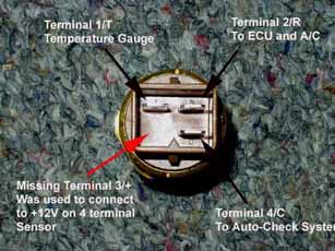 Actual
photo of the MFTS showing location of connections.
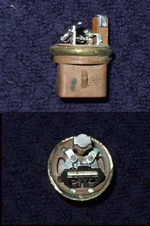
Actual
photo of the MFTS showing location of connections.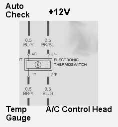 Wiring diagram of the MFTS connections, showing wiring colors