|
CIS Fuel Injection, Technical Tips, 1986-90 5000/200TQ
FUEL INJECTORS, INSERTS, AIR SHROUD CONES AND O-RINGS, LEAKY INJECTORS, Viton ® TIPPED INJECTORS
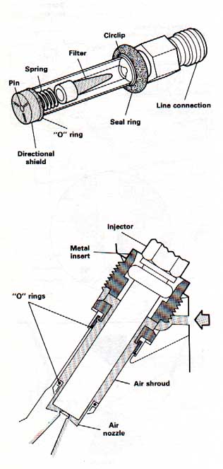
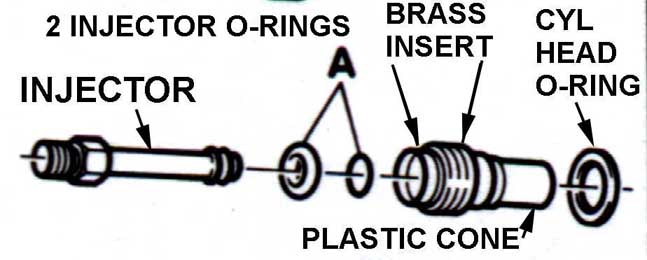
The 2 fuel injector O-rings and the brass/plastic fuel injector inserts that are screwed into the cylinder head may need to be replaced as they can cause a vacuum leak on high mileage engines. The air shrouded injectors use a two piece cylinder head injector mounting insert which consists of a threaded brass piece and a plastic air shroud cone that snaps on to the end of the threaded brass piece. The threaded brass piece and air shroud are then screwed into the cylinder head with an O-ring around the plastic cone. This O-ring around the air shroud cone seals between the cone and the cylinder head. Here are some diagrams showing the fuel injector, the 2 injector O-Rings (A), the threaded brass insert, the plastic cone, and the insert/cone O-ring which seals the insert/cone to the cylinder head.
You can test the air shrouded inserts for leaks by removing the small rubber hose from between the intake manifold and the cylinder head, and use an air compressor and regulator to apply 14psi of air pressure to the port in the cylinder head. Spray some soapy solution around the injectors/inserts in the head and check for any leaks (bubbles). Note: The later MC engine with Dual Knock Sensors, has a calibrated orifice inside this short rubber hose that connects between the intake manifold and the cylinder head.
I normally just replace the inserts and injector O-rings on high mileage cars to eliminate any possible vacuum leaks.
The fuel injector itself, is sealed and retained to the inside of the brass threaded piece using a thick green Viton ® O-ring that goes around the shank of the injector. The green Viton ® injector o-rings should be used here instead of the older black rubber ones that get hard because of the high operating temperatures and don't seal well over time. There is also a smaller diameter O-ring that seals the end of the injector down inside the air shroud cone. If you are replacing the injectors, the new injectors will come with both of these O-rings installed.
The Valve Cover will have to be removed to allow unscrewing the brass upper injector inserts and the Valve cover gasket should be replaced. Use the 1 piece rubber gasket which also comes with the half moon seal. There was a change made to the gasket in mid 1989 Model year.
When replacing the Valve Cover gasket, note that there were different Valve Cover gaskets used on the MC Engines, be sure to check the information listed in the Engine section.
Be careful when removing the brass insert as the phenolic cone can
come loose and stay down inside the head. You need a 13mm allen wrench
to unscrew these brass inserts from the cylinder head. The cone is a
bit of a pain to remove, if it comes off the brass threaded piece and
fall into the cylinder head. If the plastic cones are broken and large pieces fall into the cylinder head, you may have to remove the intake manifold to retrieve any broken pieces, not fun! The new threaded brass inserts need some blue Loctite Medium Grade liquid thread locker applied to the threads when it is installed. Torque to 18 lb-ft
INTAKE VALVE DEPOSITS
Intake valve carbon deposits can cause cold running problems as the carbon acts like a sponge, soaking up the fuel at first. You should look at the back of the intake valves when you remove/replace the injector inserts and air shroud cones. With severe carbon buildup some repair shops can use a walnut shell blasting device to clean off the carbon buildup. Lighter buildup can be removed with the use of a fuel additive or a fuel with Techron.
The plastic injector cooling air deflector has slots that should be positioned over the injector fuel lines after replacing the inserts and installing all of the injectors. This air deflector can help prevent the injectors from being blown out under boost. Don't laugh, I have seen it happen, MAJOR vacuum leak.....and fire hazard....
LEAKY INJECTORS
Leaky injectors can increase the hot/cold starting times. One way to check for leaky injectors is to remove the spark plugs and see if any fuel is leaking into the combustion chamber after the engine is shut down. Drive the car so it gets warmed up thoroughly and then shut off the engine and wait about 30 minutes to an hour. Remove the spark plugs and look down into the cylinders combustion chamber using one of those fiber optic flashlight attachments that will allow you to insert the fiber optic light pipe down into the cylinder through the spark plug hole. Using this light pipe you can actually see puddles of fuel inside the cylinder. If the spark plug tips are wet with fuel, this of course is another indication.
I have not tested whether a thorough injector cleaning using a Motorvac system or some other brute force chemo-therapy system will actually fix old leaky injectors with lousy spray patterns. The tips of the injectors may just wear out during several years and thousands of miles of use.
Dirty/clogged injectors that have lousy spray patterns and which do not atomize the fuel very well will cause poor low end performance (lousy torque) and uneven performance when cold. The Bentley manual describes the procedure for removing the injectors and checking the spray pattern.
CAUTION: You need the special fixture that allows the injectors to be inserted into individual graduated cylinders to capture the fuel during this spray pattern test. DO NOT allow the injectors to spray fuel into the open around the engine compartment! EXTREME FIRE HAZARD
Viton ® TIPPED INJECTORS
In addition to the Viton ® O-rings that seal around the injector body, there are fuel injectors that use Viton ® seals inside the tip area. According to the Bentley: The Viton ® tipped injectors carry the following part numbers
(3.2 bar version, high pressure, fine thread, Audi # 035 133 551F, Bosch # 0-437-502-043, OEM Bosch version 0-437-502-044)
(2.5 bar version, low pressure, coarse thread Audi # 026 133 551, Bosch # 0-437-502-045, or OEM Bosch 0-437-502-046)
VAPOR LOCK - HOT START PROBLEMS, INJECTOR COOLING FAN
My 86 5000CS Turbo occasionally acted like it had vapor lock after restarting the car after it sat for 15-30 min after being fully warmed up. It felt like the injector lines had lost fuel pressure as the engine would miss until it was revved up a few times. It did this every year after this oxygenated fuel showed up at the gas stations. This problem was not too bad after I replaced the injectors as some were leaking. The early ur-Quattro Coupes seem to suffer heavily from this problem.
The later 1989-90 200TQ changed to smaller diameter fuel lines to help eliminate this vapor lock problem but they also can suffer from leaky injectors which can cause hot/warm start problems. See the section above for more details.
In some cases having too high of a "system" pressure may create a high residual pressure after shut-down which can force fuel through the injectors to cause a hot start problem after the car has sat for 30 min-1 hr after getting warm. If you watch the residual pressure after shut-down you might see a pressure reading of 3.2 bar or so, but then after 5-15 min. the pressure will go UP to 3.9-4.2 bar before settling back down to 3.0 bar or so.
Sometimes replacing the injectors will eliminate this type of hot start problem even when the residual pressure creeps up after shut-down.
The Residual Fuel pressure should also be checked whenever you have hot start problems, as this can often be caused by leaks in the fuel pump check valve and other components in the system. Check above in the FUEL SYSTEM PRESSURE section for details.
The injector cooling fan thermo-switch should also be tested and verified to be working correctly to prevent hot start problems. This sensor has a single wire terminal connection and is mounted back at the rear of the engine on the exhaust heat shield near the Waste gate. Grounding the sensor wire should turn on the injector cooling fan with the engine off. The early 5000TQ's and ur-Quattro coupes used a higher temp sensor (100 or 110C) that can be replaced with the later version that comes on at a lower temp ~85C to reduce under hood temps after shut-down. This sensor has the Audi part number 034-919-369B but check with your Audi dealer in case the part number has been superseded.
The 5000T/Q and 200TQ use a slightly different injector cooling nozzle than what was used on the ur-Quattros and this newer nozzle has an additional hole on top that directs air over near the injector lines and fuel distributor. This plastic cooling nozzle is also designed to hold the injectors in the head should the injector O-rings get hard and loose. The 5000T/Q's and 200T/Q's also have a rubber cover for the fuel distributor and fuel injector lines to reduce the possibility of a fire should one of the injector lines burst.
Idle Stabilizer Valve (ISV) Control Unit Testing, CIS IDLE SPEED and IDLE MIXTURE ADJUSTMENT - (Exhaust CO%)
The idle speed should be checked and adjusted before adjusting the idle mixture. Before checking the idle speed, ensure the following: There are no vacuum leaks from the fuel injector inserts, crankcase breather hoses, valve cover gasket, turbo charger/intercooler hoses etc. , check the Intake Vacuum leak section and the "ABC's of Running High Boost" section for details.
The engine oil temp should be at or above 80C (176F), throttle valve switch is working and correctly adjusted, Idle Stabilizer Valve (ISV) Control Unit and ISV Control Unit coolant temp sensor is ok, (single wire sensor mounted on coolant outlet on cylinder head, resistance should be ~130 ohms at 176F), A/C system along with other electrical loads are turned off, the breather hoses and charcoal canister system are disconnected as outlined below. You should wait for the radiator fan to turn off during the check and adjustment procedure.
1986 to '88 5000TQ, early 89 200TQ with the Single Knock sensor MC engine
A few things need to be done before you check and adjust the idle speed and idle mixture. Disconnect the breather hose coming from the air intake boot at the valve cover tee fitting and plug this hose. (Major vacuum leak if you don't plug it!) Removing this breather hose also eliminates any crankcase fumes from affecting the mixture measurement. If the duty cycle measurement goes down a lot after reconnecting the breather hose the crankcase oil may be diluted with fuel. There is also rubber cap on another plastic tee fitting near the R/Front head lamp that needs to be removed. This cap is on a port for the charcoal canister purge line, and you need to remove this cap so the mixture adjustment is not affected by any gasoline vapors coming in from the charcoal canister. Idle Mixture Adjustment Continued: Later 200TQ's with the dual knock sensor MC designated engine
Disconnect and plug the breather hose as outlined above. The blue rubber plug on top of the round intake boot should be removed. This blue rubber boot covers a calibrated orifice to allow air to come in and bypass the air flow plate. The two charcoal canister solenoids should have the electrical connector removed from them, one is in the front portion of the round intake boot, the other one is behind/below the rear portion of the round intake boot. The electrical connectors has a spring clip that can be pushed in to allow the connector to slide off.
For all MC engines:
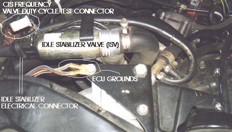
Here is a photo showing the Idle Stabilizer Valve location at the rear of the intake manifold.
Disconnect the Idle Stabilizer Valve (ISV) electrical connector and use jumper wires to connect a DMM (0-1000mA scale) in series with 'one' of the two supply wires connecting to the ISV valve, connect the other supply wire directly to the ISV. This connection scheme will allow you to measure the current flow into the ISV for checking the idle speed adjustment. Connect a tachometer to measure the engine RPM or use the dash mounted Tach.
Testing the Idle Stabilizer Valve Control Unit, Adjusting the Idle Speed, 1986 to '88 5000TQ and early 89 200TQ with the Single Knock sensor MC engine.
With the DMM connected in series with the Idle Stabilizer Valve (ISV), Turn on the ignition, the DMM should read 550 +/- 25mA. If it does read the correct mA value, then go down below to Adjust the Idle Speed section.
If NOT and If 430mA is measured, check for an open circuit between the ISV Control Unit and Terminal 1 on the Ignition Coil according to the Bentley wiring diagram. The ISV Control Unit is located under the left side of the dashboard in the auxiliary relay panel. If 0 mA is measured with the ignition key on, check for open circuit between the ISV Control Unit and the ISV Temperature sending unit, or possibly the Temperature sending unit is defective. This ISV temp sensor is the same type used for the Engine Control Unit, so go to ECU System, Engine Control Unit Temp Sensor section on details on testing this temperature sensor.
Also check for open circuit wiring between the Idle Stabilizer Valve (ISV) and the ISV Control Unit. if the wiring checks out ok then the likely culprit is a defective ISV Control Unit. Some of these ISV Control Units have intermittent solder joints inside that can be repaired if you are handy with repairing electronic items.
NOTE: The Idle Stabilizer Valve Control Unit for the earlier KH turbo engine uses the 443 907 393K part number, the one for the MC Turbo Automatic engine/vehicle which uses the 443 907 393 part number, and the one for the MC turbo 5 speed/Quattro is listed in the fiche as the 443 907 393P so be careful if you end up buying a used one. The later 1989-91 200T and 1989-90 200TQ with the dual knock sensor MC engine use a different ISV control unit, the 447 907 393B, which fits both the automatic and manual transmission cars. The Idle Stabilizer Valve (ISV)�for the KH and MC engine is the same and uses the 035 133 455F part number.
NOTE: The Deceleration solenoid/vacuum valve can stick and cause stalling during deceleration on the manual transmission vehicles. Go to ECU system page for more details on the operation of this valve.
Adjusting the Idle Speed
Once you have determined the ISV Control Unit is working ok, Start the engine and let it idle, don't forget that the engine should be warmed up, the manual transmission cars should idle at 720 +/- 50 RPM, automatic equipped vehicles should idle at 800 +/- 50 RPM. If not, then use the adjusting screw on top of the throttle body to adjust the idle speed. Now un-plug the green wire from terminal 1 on the ignition coil (86-88 5000TQ, single knock MC). This activates the idle stabilizer control unit preset value. Look at the DMM and read the mA displayed, you should see 430mA +/- 20mA. Now reconnect the terminal 1 green wire or connection and check the DMM reading again, you should see 430mA +/- but now the reading mA current reading should be fluctuating a little as the Idle Stabilizer control unit adjusts the current flow into the ISV to adjust the idle speed.
Testing the Idle Stabilizer Valve Control Unit, Adjusting the idle speed, 1989-90 200TQ's with the dual knock sensor MC engine
Check ISV control unit current: With the DMM set to measure DC current, and connected in series with the Idle Stabilizer Valve (ISV), Turn on the ignition, the DMM should read 440-500 mA. If it does, then go down to the section below for Adjusting the Idle Speed.
If it does NOT read 440-550 but reads 0 mA with the ignition key on, you need to make some DMM voltage and resistance measurements at the Idle Stabilizer (ISV) Control Unit socket. This control unit is located under the left kick panel below the instrument panel.
Unplug the ISV Control unit. Check ISV voltage supply and ground. Measure the voltage between terminal 14 (+) and 5 (-) with the ignition turned on, you should read battery voltage. If not, review the wiring diagram in the Bentley Repair Manual and check the wiring and see if the ground wiring at terminal 5 or the +12V terminal 14 supply wiring is faulty.
Check throttle switch idle connection with throttle closed and open. Measure the voltage between terminal 8 and 5 with ignition key on and with the idle switch closed (throttle valve at rest), you should read battery voltage. Measure voltage between terminal 8 and 5 with the ignition key on and the throttle open slightly to open the idle switch, you should read O volts.
If not, check the throttle switch operation (Throttle Switch) and the wiring at the throttle switch connector, also check the wiring between the switch and the ECU, and between the ECU and the ISV control unit socket. Use the Bentley Manual wiring diagram.
Check ECU engine speed signal wiring. Probe between terminals 17 and 5 using a LED test light, and when you crank over the engine, the LED test light should flash or flicker. If not, check the wiring between terminal 17 and the ECU using the Bentley Wiring Diagrams.
Check vehicle Speed signal connection. With the ignition on, probe between terminal 7 and 5 with the LED test light, the LED should light up. If not, check the wiring from terminal 7 to the instrument cluster speedometer vehicle speed signal.
Check ISV Coolant temp sensor: Use the Ohm meter function of the DMM to measure the resistance and probe between terminal 13 and 5, you should read somewhere between 70-150 ohms at ~176F coolant temp. Go to ECU System, Engine Coolant Sensors section on details on testing the ISV temperature sensor.
Check Idle Stabilizer Valve internal solenoid connections and wiring to ISV. Measure resistance between terminal 11 and 4 using the Ohm meter function, you should read ~3-8 ohms.
Check signal from A/C Compressor. Measure voltage between terminals 6 and 5 with the Ignition switched on, the A/C turned on, A/C mode in AUTO, Blower on HI, Temperature on HI, You should read approximately battery voltage.
If any of these DMM tests fail, use the Bentley wiring diagrams as mentioned to check for open or short circuits between the ISV components, the ECU and other items that interact with the ISV system. If all of the wiring checks out ok, you may have a defective ISV control unit. Some of these ISV Control Units have intermittent solder joints inside that can be repaired if you are handy with repairing electronic items.
Adjusting the Idle Speed
Start engine and let it idle, the manual transmission cars should idle at 720 +/- 50 RPM, automatic equipped vehicles should idle at 800 +/- 50 RPM. Look at the DMM and read the mA displayed, you should see 430mA +/- 20mA and fluctuating. If not, then use the adjusting screw on top of the throttle body to adjust the idle speed until you see 430mA +/- 20mA. The reading should be fluctuating because the Idle Stabilizer control unit is attempting to adjust the idle speed by regulating the current flow into the solenoid.
For all MC engines:
The CO% idle mixture adjustment is also referred to as the frequency valve "duty cycle" adjustment. The Engine Control Unit (ECU) controls the operation of the frequency valve via a changing duty cycle signal. In response to the O2 sensor voltage signal the ECU receives, the ECU changes the duty cycle controlling the frequency valve and this adjusts the fuel mixture "slightly" rich or lean as needed. The frequency valve changes the lower chamber pressure inside the fuel distributor which alters the amount of fuel sent out to each injector.
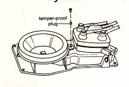
The access hole to this CO% adjustment screw is in-between the fuel distributor and the intake boot on top of the air flow metering/air cleaner assembly. This hole is plugged with a soft aluminum plug at the factory to prevent tampering.
You need to CAREFULLY drill a small hole in the plug and use some sort of a slide hammer with a sheet metal screw to pop out the plug. Instead of the plug, there may be a rubber plug with wire retainer covering this access hole. In some cases, there may be nothing covering this hole (not good!). This rubber plug is available from VW/Audi/Porsche and should be used to plug this hole after making the adjustment. This rubber plug will keep unfiltered air from entering the engine. If you are a golfer, a golf tee will also work to plug this hole....FOUR!
The idle mixture can be checked and adjusted by using two different methods.
Method 1: This involves measuring the CO% of the exhaust gas upstream of the catalytic converter with the O2 sensor DISCONNECTED by using an exhaust analyzer connected to the small metal pipe with the blue cap which is bolted to the intake manifold. This metal pipe is connected to the exhaust pipe just after the turbo. The factory spec. for the upstream idle CO% is 0.6% to 1.2%. Adjusting the mixture to the high end 1.2% provides better cold starting and initial running.
Method 2: This is done by measuring the duty cycle of the frequency valve with the O2 sensor CONNECTED. This assumes the O2 sensor is connected, working correctly and is warmed up (O2 heater working ok) and there are no vacuum leaks.
The idle speed should be adjusted correctly before making this CO% adjustment. On the single knock sensor MC engines, the green #1 terminal on the ignition coil terminal block should be disconnected as described in the Idle Speed Adjustment procedure when performing this CO% check/adjustment .
There is a small clear plastic two pin connector near the back of the intake manifold that is used to connect the dwell or duty cycle meter to, in order to measure the dwell or duty cycle of the frequency valve. Connect a dwell meter (4cyl scale) or a duty cycle meter across these two connector pins. Don't connect directly to the frequency valve to make this measurement as the reading will be incorrect. The blue/black wire is the + lead, the brown wire is the - or ground lead. Note: to convert from 4 cylinder Dwell reading to duty cycle, divide Dwell reading by 90. In other words, 45 degrees of dwell equals 45/90=50% duty cycle. In this case you are measuring the NEGATIVE duty cycle, which is the time the signal is low.
Even though this duty cycle changes back and forth 1 to 2 times per second between high and low values (42-50%) , usually the "average" duty cycle should be adjusted to be around 46%. This corresponds to a upstream CO% around 1.2%. The factory adjustment spec is 50% plus or minus 8%. Some Digital Dwell Meters or duty cycle meters will average the low and high value. The older analog dwell meters should show you the swing between the two values. Some people like to adjust this duty cycle down lower to around 38% to richen up the mixture across the entire range of airflow conditions and to ensure a rich mixture full load. I need to check the exhaust emissions while under load to verify that this 38% richer setting is ok before I can recommend it.
This CO% idle mixture adjustment is done by turning the 3mm allen screw down inside the air flow metering plate assembly. Turning the screw clockwise makes the idle mixture richer by raising the height of the fuel distributor plunger in relation to the air flow metering plate height, and this exposes more of the plunger metering slits to allow more fuel through. Turn the screw in VERY small increments, like 1/16-1/8 of a turn at a time. Turning the screw a small amount can have a large change in the idle mixture. After changing the adjustment, you should remove the 3mm allen wrench from the adjustment hole and briefly rev the engine to >3000RPM and let it idle again to settle the air flow plate position and then recheck the duty cycle reading (Method 2) or the CO% reading (Method 1)
Getting this idle mixture adjusted correctly is very important to ensure good initial cold running and is required for correct full throttle enrichment under high boost!
O2 SENSOR - OPEN LOOP AND CLOSED LOOP OPERATION
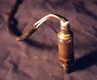
The oxygen sensor is mounted in the exhaust pipe just after the turbo exit. The O2 sensor has a internal heating element to ensure quick warm up and correct operation at idle. There are three wires going into the O2 sensor on the Audi Turbos. One ground, one +12V signal, and one for the actual O2 sensor output voltage. Here is a picture of the O2 sensor with it removed from the exhaust down pipe.
When the engine is first started when it is cold, the engine will briefly run for 1 or 2 minutes in open loop operation based on the "basic" idle mixture setting in the fuel distributor. Normally the basic idle mixture is set to be 0.6% to 1.2% Carbon Monoxide (CO) when the exhaust gas is measured up stream of the catalytic converter. Once the Oxygen (O2) Sensor warms up (Heated O2 sensor), the system will switch over to closed loop operation.
With the fuel system in closed loop operation, the O2 sensor voltage cycles up and down between ~0.1V and ~0.9V. At idle, the O2 voltage should cycle back and forth 1 to 2 times per second and when cruising, it should cycle back and forth 4 to 5 times per second. This cycling occurs because the engine computer senses the O2 voltage and then changes the frequency valve duty cycle in response.
If the O2 sensor voltage is high (rich) the computer will reduce the duty cycle percentage controlling the frequency valve, then the exhaust gas gets lean (more O2) and the O2 sensor voltage drops low, so then the computer reads this low O2 voltage and then it increases the duty cycle percentage controlling the frequency valve and then mixture gets richer again. Rich, Lean, Rich, Lean, over and over again. This is the closed loop feedback control system in operation. (only small changes in the mixture are occurring).
This switching action allows the ECU to do minor adjustments to the air fuel ratio to allow the catalytic converter to perform its job to optimize the "oxidation" of Carbon Monoxide (CO) and Hydrocarbons (HC) and the reduction of Nitrogen Oxides (NOx). The oxidation occurs when the mixture is slightly lean and more oxygen is available, and the reduction occurs when the mixture is slightly rich and less oxygen is available.
These chemical reactions that occur in the catalytic converter ensure the lowest possible emissions out the tailpipe. Catalytic converters typically operate at 60-90% efficiency depending on age. This means that the amount of exhaust emissions that enter the catalytic converter are reduced approximately by this percentage. For example, in the Audi I5 turbo engine, at idle, you typically have exhaust gas entering the catalytic converter with a Carbon Monoxide (CO) level of 1.2%, this would be reduced to 0.36% to as measured at the tailpipe with a 70% efficient converter
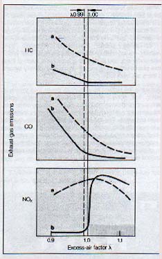
Here is a chart showing the relationship between three exhaust gases
(HC, CO, and NOx)
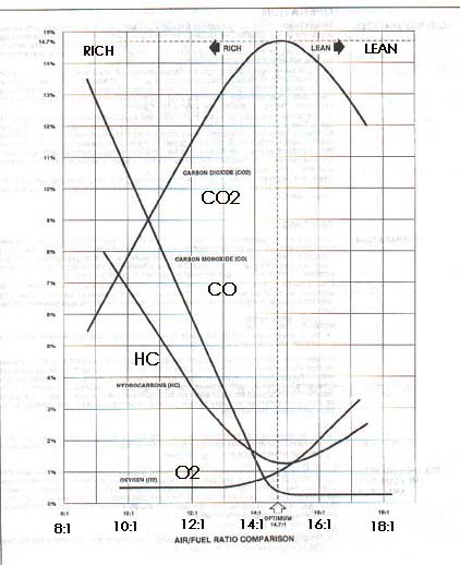
Here is another chart showing the relationship between the various exhaust gases and air/fuel ratios.
You can watch the frequency valve signal duty cycle change back and forth on an oscilloscope screen and if you connect up the O2 voltage signal on channel 2 of the o-scope you will see how the high (rich) O2 voltage will cause the frequency valve duty cycle to change in order to lean out the mixture.
If the O2 sensor wire is disconnected with the engine running, the ECU usually has a 0.45 V reference voltage on the ECU wire connecting to the O2 sensor. The ECU will switch over to a basic idle mixture setting with the O2 sensor disconnected. In the CIS fuel injection 10V Turbo engines, the frequency valve duty cycle will be set to 50% when the O2 sensor is disconnected. The ECU O2 signal wire is the large green wire with male and female spade connector under the rubber boot. This rubber boot is near the passenger side fender rim next to the fuel distributor on the 1986-88 5000T/Q, and early 1989 200TQ. The later 89-90 200T/Q with the dual knock sensors and the 1991 200T/Q's (10V and 20V engine) have this rubber boot connection on the back engine firewall area on the bracket with the other color coded connectors.
One test you can do with the O2 sensor wire connected to the ECU, is to use an oscilloscope to measure the O2 sensor voltage and then force the mixture rich with the slow addition of propane into the intake system. The O2 sensor voltage should rise up to at least 0.85 volts. Then force the mixture lean by creating a huge vacuum leak and measure the O2 voltage transition time when the voltage drops from high to low.
To quickly force the mixture lean, you can pull off a large hose from the intake manifold, or remove the oil cap from the valve cover (10V Turbo only). This will make the engine stall but you can capture the O2 voltage response on the digital oscilloscope.
Typical transition times are around 25-50ms, the rule of thumb is that the O2 sensor transition time from 0.6V to 0.3V or from 0.3 to 0.6V should be under 100ms. The O2 sensor will have a different transition time going from rich to lean than from lean to rich, if I remember correctly the rich to lean transition is slightly longer.
You can use a Digital Multimeter (DMM) to measure the O2 sensor voltage with the sensor connected to the ECU, but the meter may not respond quickly enough to see the voltage go up and down. It is important to know what the input impedance is of the meter you are connecting across the O2 sensor or for that matter across any of the ECU inputs/outputs. Most modern DMM's have a 10 Mega-ohm input impedance. Many of the older analog meters have a input impedance down below 100K ohms. These older meters "may" work once your O2 sensor is warmed up as the impedance of the O2 sensor usually drops to 5-20k ohms.
If your DMM has a "analog" type bar graph feature, you can measure the O2 voltage and see changes, as this bar graph display responds quicker and this can be used to monitor the O2 sensor voltage as it swings high and low when the ECU/fuel system is in closed loop operation.
If the DMM has a "zero" feature to zero out the bar graph reading with a voltage applied, you can connect the DMM to the O2 sensor wire and turn on the ignition before starting the warm engine. The DMM should read ~0.45V with the meter connected to the O2 sensor wire with the ignition on, but with the engine not running. Now zero out the 0.45V reading, and start the engine. The DMM bar graph should oscillate up and down around this 0.45V reference voltage 1 to 2 times per second, indicating that the system is in closed loop operation.
It is important to understand that if the DMM or oscilloscope shows the O2 sensor voltage stuck high or low and not oscillating up and down, that the sensor may be working correctly. The real problem may be mechanically related (lean condition from vacuum leak) or engine fuel system may have a problem (rich mixture from fuel pressure being too high). When the engine is running very lean (low O2 voltage) or is running very rich (high voltage) the ECU can not tweak the mixture enough to compensate for these problems. The O2 sensor heating element could also be defective, and this can cause a cold O2 sensor at idle with no fluctuation in output voltage.
O2 SENSOR PROBLEMS
One problem that affects the O2 sensor operation is contamination or poisoning by silicone, this shows up as a fine white powder on the tip of the sensor and will reduce the voltage output of the sensor when the mixture is rich, and this will cause a loss of fuel economy and increased CO and HC emissions. You may also see a negative voltage developed under lean operation when the sensor is poisoned by silicone. This poisoning causes the sensor to see a lower proportion of Oxygen.
The slots in the tip of the O2 sensor can also get partially clogged with carbon which will increase the response time. This will cause the O2 voltage change to slow way down, taking 3-4 seconds to go up and down, instead of changing in less than a second. This slow response can cause a varying idle speed and varying idle mixture. This slow response will show up as a varying idle speed and varying idle mixture. The exhaust gas Carbon Monoxide (CO) reading will not be steady at idle when read by an exhaust analyzer. This can also cause some light surging under light acceleration with the engine cold and when fully warmed up under cruise conditions.
There are several Society of Automotive Engineers (SAE) articles that have been published since the early 70's that describe in the utmost detail the operation of these O2 sensors. Each year SAE publishes 2-3 thousand articles covering the various automotive areas and is required reading for anyone looking for in-depth technical information on automotive systems.
Here is an excerpt from the 1976 SAE article #760287 "Closed Loop Control of Lean Fuel-Air Ratios using a temperature compensated Zirconia Oxygen Sensor"
"The sensor is based on the electro-chemical potential developed across a zirconium dioxide solid electrolyte when its two electrodes are exposed to differing oxygen concentrations. One electrode is exposed to the constant oxygen pressure of ambient air and the other to the oxygen pressure of the exhaust gas which varies with equivalence ratio. A voltage is produced which is a function of the equivalence ratio."
Most university libraries have the articles going many years back on micro-fiche and they should have an index that lists all the articles by subject, author and number. Go to O2 Sensor and Emission Article Listing for details. Bosch Generic 3 Wire Oxygen Sensor
Bosch makes a replacement 3 wire O2 sensor which is sold in large quantities and carries a low price. This generic O2 sensor can be used in the Audis if you use your original wiring and connectors and splice it to the wires on the new oxygen sensor.
I use the smaller gauge (red) butt type crimp connectors to splice the original O2 sensor wiring to the new generic O2 sensor. I cut the O2 sensor wires to have different lengths, so I can space the crimp connectors in different locations to allow them to slide inside the original wire sleeve to protect them from the elements.
FUEL INJECTION QUESTIONS- MB, Early and Late MC Engines
The MB engine CIS system appears to be very similar to what was used on the mid 89-90 200TQ US model cars, with the higher compression dual knock sensor MC engine.
The 86-88 5000TQ and early 89 200TQ (single knock sensor MC engine) have a system pressure regulator inside the fuel distributor metering head. In mid 1989 when they went to the higher compression dual knock sensor MC engine they removed that internal system pressure regulator inside the fuel distributor and used a remote mounted system pressure regulator like the one described for the European MB engine. The system pressure listed for MC engines from the Bentley is supposed to be between 5.8-6.6 bar but I don't know if the Bentley info was updated to correctly reflect this change to the remote mounted pressure regulator.
The part number for the system pressure regulator that is used on my 89 200TQ car is a 034-133-534L. My fuel pressure regulator has a hose connected to it but I believe the hose just goes down into the air filter housing, and is open to the atmosphere. This remote mounted system pressure regulator looks similar to the one used on the NA CIS-E-III systems but on these systems they did not use a warm up regulator or the frequency valve. They had a differential pressure actuator that is mounted on the side of the fuel distributor and used an electronically controlled current to tweak the mixture for cold running mixture enrichment and for O2 sensor mixture tweaking. The CIS-E-III system pressure is spec'd to be between 6.1-6.5 bar.
The Bentley manual for my late 89 200TQ with the dual knock sensor MC engine does not document this change to the different fuel pressure regulator very well at all. This system seems to be a bit of a bastardization of the newer CIS-E-III system parts and the older MC single knock sensor CIS system.
The fuel distributor used on my late 1989 dual knock sensor MC engine, has an Audi# 034-133-481J (Bosch # 0 438 100 153) , but has a plug where the internal pressure regulator normally is installed. The Bosch rebuilt part number is "FD77X" for this fuel distributor. The air flow metering plate used in the dual knock sensor MC engine is a Audi # 034-133-353L (Bosch # 0 438 121 064).
I ran across one odd ball setup, that came out of an early 1989 200TQ with the single knock sensor MC engine. It had the Bosch # 0 438 121 053 Air flow meter assembly that was used in the 1986-88 5000TQ, but had the later fuel distributor Bosch 0 438 100 153 with the internal pressure regulator installed.
The single knock MC engines (1986 1/2 to 1988 5000TQ) uses the Bosch part number (Bosch # 0 438 100 147) for the basic fuel distributor, with the internal pressure regulator. The Audi replacement part number is 034-133-481C. (Rebuilt Bosch part number "FD63X"). The Air Flow Metering plate on the Single Knock MC is a Audi 034-133-353D (Bosch # 0 438 121 053)
The single knock MC engines used in the first 1986 Model year 5000T/Q's with early production dates (Bosch lists 1/85 to 7/85 production dates) used a fuel distributor Bosch # 0 438 100 123 (Rebuilt FD70X) with the old style banjo fitting fuel injector lines and used the Bosch 0 438 140 026 warm up regulator. It is shown to use the Bosch # 0 438 121 040 air flow metering assembly.
This same fuel distributor 0 438 100 123 (Rebuilt FD70X) is also shown as the replacement for the 1983-85 ur-quattro with the "WX" engine although the "WX" engine uses a different warm up regulator, Bosch 0 438 140 094. The WX engine in the ur-quattro also used a different air flow metering assembly, Bosch # 0 438 120 193 (1984-85 ur-quattro), or the 0 438 120 146 in the 1983 ur-quattro.
The warm up regulator used on the dual knock sensor MC engine is a Audi # 034-133-403A, Bosch 0 438 140 157. This same warm up regulator was used on the earlier 1986 1/2 to 1988 5000TQ MC engines. The Control pressure with the engine oil temp between 50-70 degrees C is supposed to be 3.4-3.8 bar. The cold 25 C control pressure is spec'd to be 1.6 bar.
These warm up regulators have a vacuum port that is capped off with a little black dust cap that has a slot in it which keeps out water etc, but still allows atmospheric pressure in to the regulator chamber. The lower atmospheric pressure acting on the internal diaphragm effectively increases the control pressure on top of the fuel metering plunger at higher altitudes and provides some altitude compensation to help lean out the mixture.
My understanding is that the metering valve control pressure is regulated for the most part by the warm up regulator but I imagine the system pressure regulator does do some minor tweaking to the system pressure at different altitudes.
All of these systems use the frequency valve to tweak the overall mixture at mid-full throttle, (low to high boost levels). In the US the frequency valve is also used to tweak the mixture slightly from the O2 sensor feedback signal.
Copyright © SJM Autotechnik™ , all rights reserved Return to CIS-Fuel Injection page. Return to SJM Autotechnik™ main page.
|
| About Us Privacy Policy Terms of Use Links Customer Service Safety Information Home |